
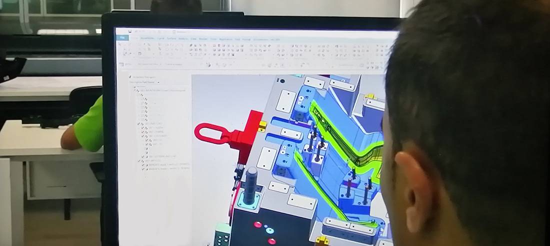
Why Partner with FMS for Mold Design?
FMS Mold Design combines decades of profound engineering expertise with state-of-the-art CAD technology to deliver high-precision tooling solutions. Supported by advanced data conversion tools and high-speed connectivity, our technical infrastructure makes global communication effortless and highly secure.
Real-Time Collaborative Engineering
We have redefined remote collaboration. Through our cloud-connected design workflows, your team can engage in real-time design reviews with our engineers at any time. We function precisely like an internal extension of your own design department—a high-touch approach that drives exceptional client satisfaction worldwide.
 FMS Mold Design Team delivers high-value, high-precision engineering solutions by seamlessly combining technical expertise with cost-effective execution. Our comprehensive services include mold feasibility studies, complete mold design and detailing, plastic part design and development, and advanced solid modeling.
Our Expertise & Capacity
The FMS engineering team consists of 10 dedicated designers, each bringing a minimum of 15 years of hands-on experience in mold design, manufacturing, and injection molding. All team members possess robust CAD/CAM/CAE competencies.
Our Design Director, David Zhang, leverages nearly 30 years of industry experience and a strong academic background in engineering. He possesses a profound understanding of European and American mold design and manufacturing standards (HASCO, DME, etc.). This deep integration of “real-world” manufacturing knowledge ensures every design we deliver is fully optimized for production, reducing lead times and costly modifications.
A Collaborative Partnership
We operate as a seamless extension of our clients’ internal engineering teams. Thanks to our diverse portfolio and decades of cross-industry experience, we adapt quickly to unique project requirements. We work closely with your engineers to deliver reliable, high-quality designs that strictly align with your standard operating procedures.
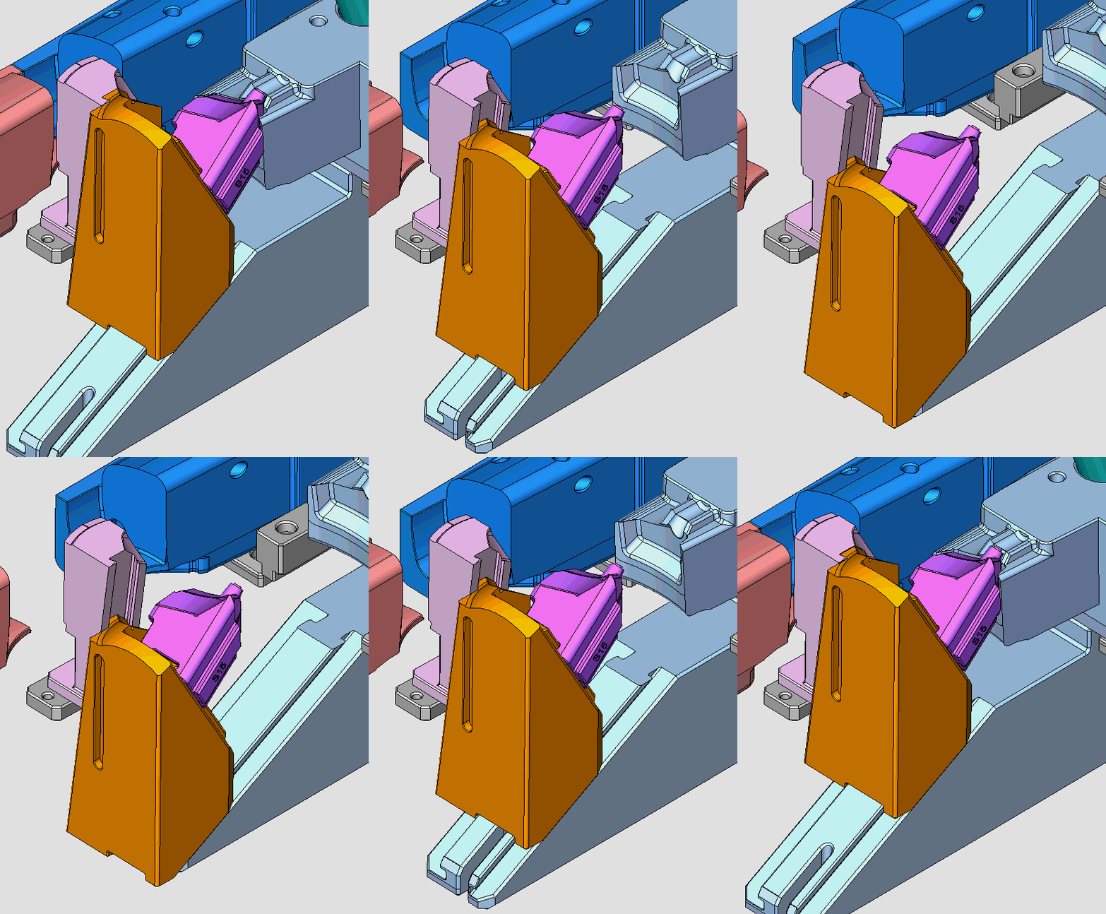
Value-Added Services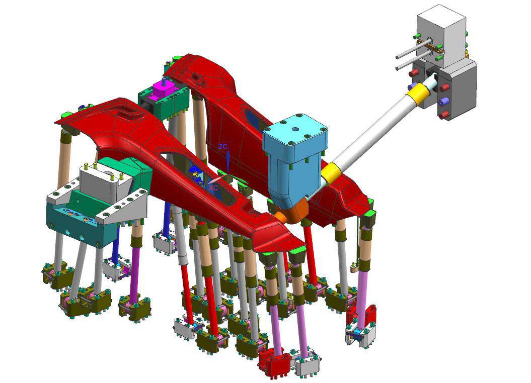
At FMS, our engineering team goes beyond standard mold design to deliver comprehensive, end-to-end technical support. Leveraging our deep industry expertise, we act as an extension of your team to provide specialized value-added services that optimize your production and fill internal capability gaps.
Our extended capabilities include:
Design for Manufacturing (DFM) and Mold Feasibility Studies / Offshore Mold Design and Third-Party Design Verification / On-Demand Engineering Resources (Additional Design Capacity)
Component Optimization Support (Assistance with Part Design) / Reverse Engineering
Design for manufacture /Mold Feasibility Studies / Designs for Off Shore Mold/Checking Designs / Additional Design Capacity /Assistance with Part Designs / Reverse Engineering
 Product Scope: Armed with a rich legacy in industrial design, our team delivers high-impact solutions across highly regulated and complex sectors. Our cross-industry footprint spans Medical Devices, Aerospace, Robotics, and Automotive, as well as Consumer Electronics, Smart Home Appliances, Workplace Technologies, and Commercial Toys. We seamlessly translate specialized technical requirements into market-ready product excellence.
Design & Engineering Flexibility
Every manufacturer operates on a unique ecosystem integrating mold design with production. At FMS, our engineering team seamlessly bridges design with advanced manufacturing methodologies. We provide fully customizable deliverables, ranging from 2D component drawings and CAD formats to precise 3D surfaces and comprehensive solid CAD data. Whether your project requires only a 2D assembly for rapid quoting or full solid CAD files with detailed hardware, cooling channels, and lifters, we adapt to your workflow. With robust data translation capabilities, we ensure seamless format compatibility—delivering exactly what you need, how you need it.
 Mold Design & Engineering Process
Robust mold design is the foundational element of a product’s manufacturing success. By engaging with our engineering team early in the design cycle, we help you optimize part geometry, mitigate manufacturing risks, and reduce overall tooling costs.
We understand that early-stage designs involve highly sensitive proprietary information. We treat your Intellectual Property (IP) with the strictest confidentiality, and we are fully prepared to execute a Non-Disclosure Agreement (NDA) before reviewing your concepts. Mutual trust is the cornerstone of our engineering partnerships.
Phase 1: RFQ & Initial Feasibility Assessment
To provide an accurate initial quotation and perform a preliminary Design for Manufacturing (DFM) review, we require the following baseline data:
• Product Geometry: Part drawings, 3D concept models, rough sketches, or physical prototypes.
• Application Environment: Product specifications, including mechanical performance requirements and operating conditions.
• Resin Specification: Intended base material (if predetermined).
• Production Volume: Estimated Annual Usage (EAU) and target production batch sizes to determine the appropriate tooling class (e.g., SPI Class 101 vs. Class 103).
During this phase, our engineering team collaborates with you to evaluate the part design for manufacturability, identifying opportunities to optimize cycle times, eliminate cosmetic defects, and minimize initial tooling investments.
Phase 2: Tooling Design & Engineering Validation
Upon successful acceptance of the quotation and project award, we require a comprehensive data package to initiate the formal mold design process:
• 2D Engineering Drawings: Fully dimensioned prints in .DWG or .DXF format.
• 3D CAD Data: Native CAD files or universal formats (.STEP, .IGES, or .X_T Parasolid).
• Material & Esthetics: Final confirmation of the raw material resin, grade, and color (Pantone/RAL or texture requirements).
• Critical-to-Quality (CTQ) Dimensions: A maximum of 5 key inspection measurements for quality control tracking.
• Project Governance: Designated primary engineering and commercial contacts for technical queries and milestone updates.
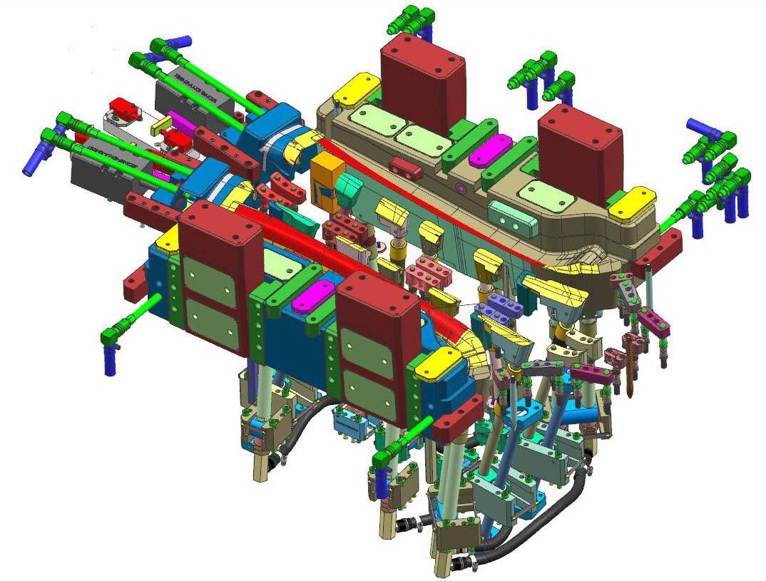 How We Execute Mold Design
Our process begins by gathering all necessary project data to provide an accurate initial quotation. We then perform a comprehensive Design for Manufacturability (DFM) review to optimize the part for production and identify potential cost savings. Following this, we generate a detailed Mold Design Specification (MDS). This guide outlines all critical requirements, including tool specifications, design standards, steel types, standard components, resin selection, shrinkage allowances, and processing parameters.
This specification guide is shared across our design, project management, and production engineering teams to ensure absolute consistency from concept to final manufacturing. Throughout production, we enforce a strict quality control workflow to maintain seamless data integrity between our 3D design models and CNC programming.
Our Stage-Gate Mold Design Process:
1. Mold Specification & Requirement Definition
2. Preliminary Tool Schematic & Concept Layout
3. Schematic Review & Customer Approval
4. Full 3D CAD Design
5. Detailed 2D Engineering Drawings & Manufacturing Documentation
The 3D geometry must be clean. The fast pace of mold making today makes it essential to have efficient, reliable software. The days of vague sketches, or toolmakers making up the design as they go are long gone. There are many excellent companies that offer high end software programs for designing molds, dies, and just about any kind of tooling you can imagine.
CNC machines need clean geometry to run properly. If the design is sloppy and the translation of different software messy, the end result will show it. Plus, the operator will have a much easier time running the programs with clean geometry.
Having an integrated mold design and production team helped ensure all issues were identified early in the tooling design process instead of after production commenced. When evaluating new contract manufacturers, a well-designed supplier survey tool should include detailed questions that look at the processes and solutions that those suppliers under consideration have used to address challenging product development projects.
The materials you use for your injection molding products are essential when it comes to the cost of production and the quality and durability of the finished product. Make sure that you devote plenty of time, energy and research to finding materials that are most suitable for your components and will result in the highest quality finished products. Different materials respond differently to the injection molding process and it’s important that you know what to expect when it comes to shrinkage, minimum wall thickness, cooling rates, and durability.
Injection molding isn’t a simple process, and as many of us know, it can sometimes take quite a bit of trial and error to get your injection molding designs just right. And while every new design requires several iterations between initial conception and production, there are always a set of correct mold design standards you need to do to increase the chances of your design becoming a successful product.
what can you do to improve mold designs, and why is the design important? The initial mold design is vital for the whole manufacturing process. Imagine this—you have designed a product mold and manufacturing has begun. As the process starts, it transpires that the molten plastic is not filling the mold properly, and the finished item is difficult to remove from the mold.
When creating a mold design, remember that someone else must then interpret your designs and create a working system. It is therefore important to be concise and clear. Omit nothing—any instruction, measurement, or footnote should be included. If you create an unclear mold design, the manufacturer or engineering service could waste time deciphering your work just to understand what you require. 3D drawings can have things included such as measurements and notes—be as detailed as possible and leave nothing to chance.
It is important to get the mold design right. Mold designing is the most important aspect of this type of manufacturing. It is the main thing that a business should concentrate on—this is why it’s important to understand the nuances of mold design, and how to get it right.
Designing the mold and its various components (referred to as tooling) represents a highly technical and often complex process that requires high precision and scientific know-how to produce top-quality parts with tight dimensions. For example, the proper grade of steel must be selected so components that run together do not wear out prematurely. Steel hardness must also be determined to maintain the proper balance between wear and toughness. Waterlines must be well-placed to maximize cooling and minimize warping. Tooling engineers also need to calculate gate/runner sizing specifications for proper filling and minimal cycle times, as well as determining the best shut-off methods for tooling durability over the life of the program.
in a mold design, a variety of gate types exist, and the usage of gates that are incompatible with the material to be injected or the product’s design can cause a variety of issues to arise.
Direct gates are the most straightforward gate design available. These are best suited for use in simple molds with only one cavity. They are known to leave a noticeable gate mark upon runner removal, but work well for their intended purpose.
Fan gates minimize strain nearest the gate by providing a wider dispersion area. These are best suited to creating large parts relatively quickly.
Straight top gates allow for products to be produced with no surface inconsistencies on their sides. Surface finishing on parts molded through the use of these gates can be cumbersome.
Center diaphragm gates make molding concentric pieces particularly easy, but affect the finishing process inversely.
Tab gates redirect shear stress from the injection molding process to a removable tab instead of the part in production itself. This type of gate helps drastically in the production of pieces with particularly slim profiles, but makes finishing processes more tedious.
Mold flow analysis of injection molds is a pivotal, though often overlooked, facet to consider for optimal results. This process is handled through the use of specialized software that predicts potential issues and pitfalls that can arise given a particular mold design and material choice.
Problems with mold flow usually result in defects such as “knit lines” (also known as weld or transfer lines). Such lines are a type of discoloration that occurs where two separate flow fronts meet.
The following mold design factors are contributors to this issue arising:
Insufficiently large injection gates impeding the flow of material unevenly.
Poor injection gate placement leading to uneven flow during the injection process.
An excessive number of gates introducing multiple points of failure to the injection process.
Any of the above can result in “knit lines” on final products, but mold flow analysis prior to mold machining can keep these issues from cropping up at all in iteration and production.