
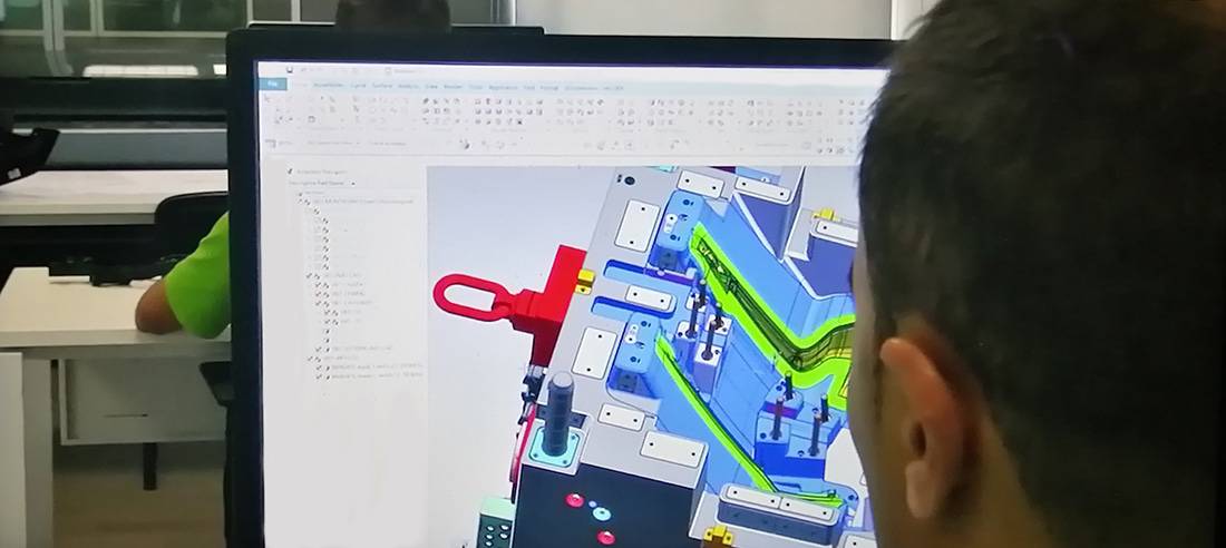
Why Partner with FMS for Mold Design?
FMS Mold Design combines decades of profound engineering expertise with state-of-the-art CAD technology to deliver high-precision tooling solutions. Supported by advanced data conversion tools and high-speed connectivity, our technical infrastructure makes global communication effortless and highly secure.
Real-Time Collaborative Engineering
We have redefined remote collaboration. Through our cloud-connected design workflows, your team can engage in real-time design reviews with our engineers at any time. We function precisely like an internal extension of your own design department—a high-touch approach that drives exceptional client satisfaction worldwide.
 FMS Mold Design Team delivers high-value, high-precision engineering solutions by seamlessly combining technical expertise with cost-effective execution. Our comprehensive services include mold feasibility studies, complete mold design and detailing, plastic part design and development, and advanced solid modeling.
Our Expertise & Capacity
The FMS engineering team consists of 10 dedicated designers, each bringing a minimum of 15 years of hands-on experience in mold design, manufacturing, and injection molding. All team members possess robust CAD/CAM/CAE competencies.
Our Design Director, David Zhang, leverages nearly 30 years of industry experience and a strong academic background in engineering. He possesses a profound understanding of European and American mold design and manufacturing standards (HASCO, DME, etc.). This deep integration of “real-world” manufacturing knowledge ensures every design we deliver is fully optimized for production, reducing lead times and costly modifications.
A Collaborative Partnership
We operate as a seamless extension of our clients’ internal engineering teams. Thanks to our diverse portfolio and decades of cross-industry experience, we adapt quickly to unique project requirements. We work closely with your engineers to deliver reliable, high-quality designs that strictly align with your standard operating procedures.
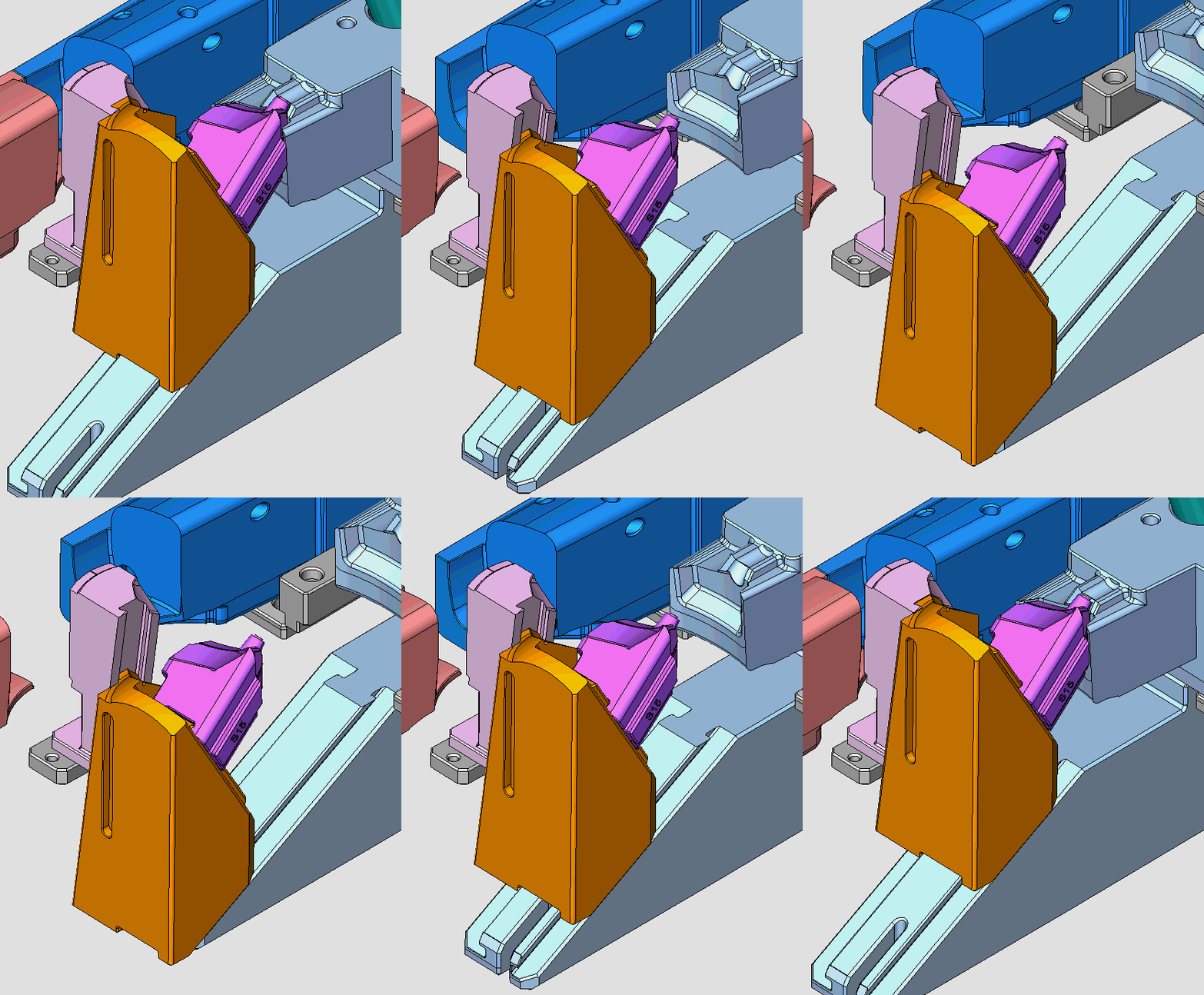
Value-Added Services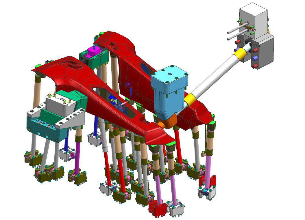
At FMS, our engineering team goes beyond standard mold design to deliver comprehensive, end-to-end technical support. Leveraging our deep industry expertise, we act as an extension of your team to provide specialized value-added services that optimize your production and fill internal capability gaps.
Our extended capabilities include:
Design for Manufacturing (DFM) and Mold Feasibility Studies / Offshore Mold Design and Third-Party Design Verification / On-Demand Engineering Resources (Additional Design Capacity)
Component Optimization Support (Assistance with Part Design) / Reverse Engineering
Design for manufacture /Mold Feasibility Studies / Designs for Off Shore Mold/Checking Designs / Additional Design Capacity /Assistance with Part Designs / Reverse Engineering
 Product Scope: Armed with a rich legacy in industrial design, our team delivers high-impact solutions across highly regulated and complex sectors. Our cross-industry footprint spans Medical Devices, Aerospace, Robotics, and Automotive, as well as Consumer Electronics, Smart Home Appliances, Workplace Technologies, and Commercial Toys. We seamlessly translate specialized technical requirements into market-ready product excellence.
Design & Engineering Flexibility
Every manufacturer operates on a unique ecosystem integrating mold design with production. At FMS, our engineering team seamlessly bridges design with advanced manufacturing methodologies. We provide fully customizable deliverables, ranging from 2D component drawings and CAD formats to precise 3D surfaces and comprehensive solid CAD data. Whether your project requires only a 2D assembly for rapid quoting or full solid CAD files with detailed hardware, cooling channels, and lifters, we adapt to your workflow. With robust data translation capabilities, we ensure seamless format compatibility—delivering exactly what you need, how you need it.
 Mold Design & Engineering Process
Robust mold design is the foundational element of a product’s manufacturing success. By engaging with our engineering team early in the design cycle, we help you optimize part geometry, mitigate manufacturing risks, and reduce overall tooling costs.
We understand that early-stage designs involve highly sensitive proprietary information. We treat your Intellectual Property (IP) with the strictest confidentiality, and we are fully prepared to execute a Non-Disclosure Agreement (NDA) before reviewing your concepts. Mutual trust is the cornerstone of our engineering partnerships.
Phase 1: RFQ & Initial Feasibility Assessment
To provide an accurate initial quotation and perform a preliminary Design for Manufacturing (DFM) review, we require the following baseline data:
• Product Geometry: Part drawings, 3D concept models, rough sketches, or physical prototypes.
• Application Environment: Product specifications, including mechanical performance requirements and operating conditions.
• Resin Specification: Intended base material (if predetermined).
• Production Volume: Estimated Annual Usage (EAU) and target production batch sizes to determine the appropriate tooling class (e.g., SPI Class 101 vs. Class 103).
During this phase, our engineering team collaborates with you to evaluate the part design for manufacturability, identifying opportunities to optimize cycle times, eliminate cosmetic defects, and minimize initial tooling investments.
Phase 2: Tooling Design & Engineering Validation
Upon successful acceptance of the quotation and project award, we require a comprehensive data package to initiate the formal mold design process:
• 2D Engineering Drawings: Fully dimensioned prints in .DWG or .DXF format.
• 3D CAD Data: Native CAD files or universal formats (.STEP, .IGES, or .X_T Parasolid).
• Material & Esthetics: Final confirmation of the raw material resin, grade, and color (Pantone/RAL or texture requirements).
• Critical-to-Quality (CTQ) Dimensions: A maximum of 5 key inspection measurements for quality control tracking.
• Project Governance: Designated primary engineering and commercial contacts for technical queries and milestone updates.
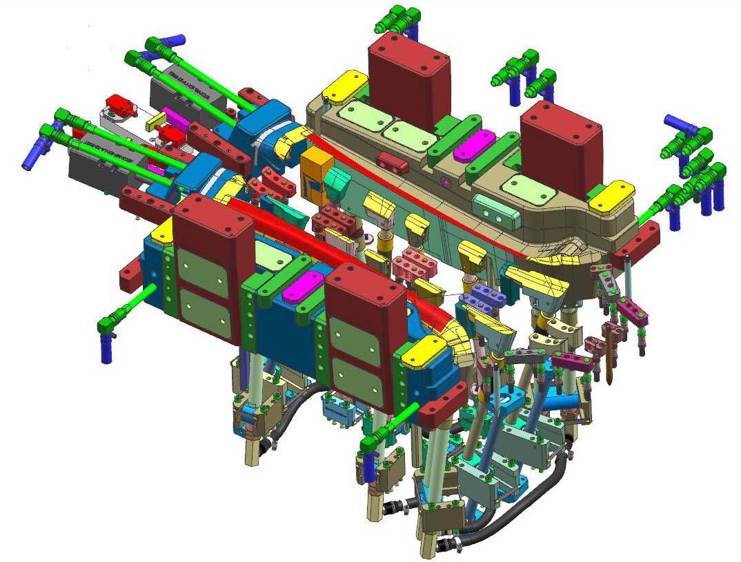 How We Execute Mold Design
Our process begins by gathering all necessary project data to provide an accurate initial quotation. We then perform a comprehensive Design for Manufacturability (DFM) review to optimize the part for production and identify potential cost savings. Following this, we generate a detailed Mold Design Specification (MDS). This guide outlines all critical requirements, including tool specifications, design standards, steel types, standard components, resin selection, shrinkage allowances, and processing parameters.
This specification guide is shared across our design, project management, and production engineering teams to ensure absolute consistency from concept to final manufacturing. Throughout production, we enforce a strict quality control workflow to maintain seamless data integrity between our 3D design models and CNC programming.
Our Stage-Gate Mold Design Process:
1. Mold Specification & Requirement Definition
2. Preliminary Tool Schematic & Concept Layout
3. Schematic Review & Customer Approval
4. Full 3D CAD Design
5. Detailed 2D Engineering Drawings & Manufacturing Documentation
Injection molds are products made of durable and hard metals such as stainless steel, steel or aluminum and can be reused for many years. Injection mold design is one of the most common types of molding used today for both consumer products and engineering applications. Almost every plastic product you see around is produced using injection molding. The reason for this is related to the production of the same parts in very high volumes with the cost per part of the technology. However, the initial costs of injection molding processes are high, as special tooling molds are needed. Nevertheless, the serial production stages of the part after the design are largely sufficient to cover the initial costs and even more.
How to Design an Injection Mold?
While designing an injection mold, there are costs such as mold materials (steel or aluminum), accuracy tests (prototype studies, full-scale production molds), and the complexity of the geometric structure of the mold. The injection molding method accounts for more than 40% of all plastic parts produced on a global basis each year. Before starting the mold design, the material of the part is selected, the production methods are determined, and the 3D geometry and tolerance technical drawing of the part product to be produced is drawn. The number of chambers of the mold is determined within the information such as monthly production, production information, investment budget and cycle time. The principles of injection mold such as cooling principles, runner and pusher types are determined respectively. After understanding the basic principles of the mold and taking orders, detailed designs of the mold can be started. The movement sequence, working principle and steps of mold designs made in 3D can be analyzed. After the mold designs are finished, the materials are ordered and mold production is started. The process becomes ready by completing the mold trial, and approval of the mold and the part, in the final process.
Injection Mold Design Advantages and Disadvantages
Injection molding is a well-established production technology with a long history.
It is a type of molding that constantly develops and improves its existence with new technological developments. However, this type of molding has some advantages and disadvantages.
Injection Mold Design Advantages:
It provides high-volume plastic production.
Thanks to its wide material range, it offers a variety of materials with different physical properties.
With high productivity, a single mold accommodates multiple parts and this phase can further increase production processes and capacities.
This type of molding can be repeated quite a lot.
Products that do not require finishing can be produced with a perfect visual appearance.
Injection Mold Design Disadvantages:
The main economic limitation of this type of molding is the high initial costs for the tooling. Making a special mold for each geometry part increases the initial costs.
Design changes after a mold has been produced are quite costly.
Delivery times can sometimes take longer than necessary.
The basic construction of a mold consists of a cavity and a core. The cavity is a void for the formation of the external surfaces of the injection molded part. The core is the inverse that forms the internal structures and surfaces.
Two-Plate Molds
Two-plate molds are the most common injection molding tooling because they’re versatile and cost-effective. They’re comprised of two plates: a cavity mold plate and a core mold plate. The cavity mold plate provides entry points for the molten plastic to flow from the injection unit to the mold via a sprue, and then to the runner and gate. Two-plate molds also have a gate connected to the side of the cavity (the void within the injection mold) that is the negative of the desired plastic component’s geometry.
Three-Plate Molds
Three-plate injection molds offer extra flexibility in gate positioning and reduce post-processing because they don’t require manual excess material removal. A three-plate mold differs from a two-plate mold because it has more than one parting line and three distinct plates: the clamping/stationary plate, the center plate, and the front cavity/moving plate.
With this construction, the gate connects to the base of the cavity to allow for an even distribution of molten plastic. Three-plate injection mold tooling is advantageous for center-gated parts, but due to high shear rates, they aren’t recommended for shear-sensitive materials.
Overmolds
Overmolding is a specific type of injection molding that utilizes two molds to produce a part with different plastics molded together as one unit. The two molds can be 2-plate or 3-plate molds — typically the harder “substrate” plastic is molded first and then is inserted into the overmold tooling to add a second layer of plastic, often elastomeric in nature, to the part. Overmolding is used for ergonomic and aesthetic purposes in part molding.
One of the first things to specify when designing tooling for an injection molded part is the overall size of the mold block.
Choose too big of a mold and you waste money on excess materials and machining.
Choose too small of a mold and your part may not be oriented in the most optimal way, which increases risk of premature mold failure.
Simply put, your mold block size should be just slightly larger than necessary and leave at least a 10 mm gap between the part’s exterior wall and the exterior mold block walls.
Carefully Choose Materials Suitable for Your Mold Design
Different injection molding materials offer varying properties. For example, some injection molding materials provide more dimensional stability than others. Similarly, some bond better with adhesives than others. Material design considers the following: temperature, pressure, biological and chemical interactions.
Thermoplastic resins can be broadly classified into amorphous and semi-crystalline. While semi-crystalline thermoplastics offer better chemical and electrical resistance, their amorphous counterparts are much more dimensionally stable and more resistant to impact. Material selection can affect the required tolerance level or certain features, like wall thickness.
Starting your mold design comes with ten major considerations.
Material Selection
Wall Thickness
Transitions
Corners
Draft
Ribs and Bosses
Tolerances
Parting Lines
Gates
Ejector Pins
The basic construction of a mold consists of a cavity and a core. The cavity is a void for the formation of the external surfaces of the injection molded part. The core is the inverse that forms the internal structures and surfaces.
Two-Plate Molds
Two-plate molds are the most common injection molding tooling because they’re versatile and cost-effective. They’re comprised of two plates: a cavity mold plate and a core mold plate. The cavity mold plate provides entry points for the molten plastic to flow from the injection unit to the mold via a sprue, and then to the runner and gate. Two-plate molds also have a gate connected to the side of the cavity (the void within the injection mold) that is the negative of the desired plastic component’s geometry.
Three-Plate Molds
Three-plate injection molds offer extra flexibility in gate positioning and reduce post-processing because they don’t require manual excess material removal. A three-plate mold differs from a two-plate mold because it has more than one parting line and three distinct plates: the clamping/stationary plate, the center plate, and the front cavity/moving plate.
With this construction, the gate connects to the base of the cavity to allow for an even distribution of molten plastic. Three-plate injection mold tooling is advantageous for center-gated parts, but due to high shear rates, they aren’t recommended for shear-sensitive materials.
Overmolds
Overmolding is a specific type of injection molding that utilizes two molds to produce a part with different plastics molded together as one unit. The two molds can be 2-plate or 3-plate molds — typically the harder “substrate” plastic is molded first and then is inserted into the overmold tooling to add a second layer of plastic, often elastomeric in nature, to the part. Overmolding is used for ergonomic and aesthetic purposes in part molding.
The injection molding process is widely used in large volume production as it produces comparatively low scrap production and has high repeatability. The versatility of the injection molding process demands much broader design considerations. Most of the design considerations will be made on the mould after setting out the product requirements.
Some of the factors that affect the injection molding design include: how the part will be used (singular product or for assembly), its dimensional and mechanical requirements, and its ability to withstand elements such as chemicals or pressure.
Tips for Injection Mold Tooling Design
Mold Block Size
One of the first things to specify when designing tooling for an injection molded part is the overall size of the mold block.
Choose too big of a mold and you waste money on excess materials and machining.
Choose too small of a mold and your part may not be oriented in the most optimal way, which increases risk of premature mold failure.
Simply put, your mold block size should be just slightly larger than necessary and leave at least a 10 mm gap between the part’s exterior wall and the exterior mold block walls.
Parting Line Locations
Parting line location is dependent upon the part’s orientation within the mold block volume. Follow these tips to determine the optimal parting line orientation for your injection molding tooling:
Strategically place parting lines such that your ejector pins can best eject the part from the mold.
Select a parting line location that reduces the amount of hand-loaded (removable and floating) inserts.
Leverage parting lines for placement of required hand-loaded inserts. For example, removable inserts for threaded features are not suited to withstand a straight pull ejection.
Consider using floating inserts placed through a parting line face to replace a side action component (if possible), such as for a through hole in the part.
Remember that gates should be placed on the parting line so that the location functions well for both the gates and the parting line.
Locate the parting line to reduce undercuts that complicate part removal and may require additional removal mechanisms.
Pro-tip: try a raised parting line by creating a recessed area away from the parting edge. This raised parting line significantly increases clamp tonnage control and provides a better seal for low viscosity plastic.
Designing for Part Ejection
Here are our main tips for designing molds that make beautiful parts and eject them cleanly:
Pin Location
Determining ejector pin locations may seem simple: make sure that all locations are covered by plastic material. However, ensuring that the pin locations are thoroughly covered is a bit more complex. Try to incorporate ejector pin location into the component’s design — it’s natural for the ejector pins to leave marks on the plastic component’s surface, but the marks can be integrated into the part’s aesthetics.
Ejector pins can be utilized to perform venting at locations where there are air traps, and they also self-clean with each ejector stroke.
Draft Angle
Ensure the correct draft angle on the walls of the mold for easy plastic component ejection. We recommend a minimum of 0.5 degrees to around 2 degrees. The optimum target value for most cases is a draft angle of 1.5 degrees for depths of up to 2 inches. A good rule of thumb is to add on an additional degree of draft for each additional inch of depth.
Also, increase draft angle for parts with texture. Both the injection mold tooling and injection molded part design must incorporate sufficient draft angles or you risk the part getting stuck in the mold.
Ejection Method
Consider all of the possible ejection methods available. You can use a single method or a combination of methods such as ejector pins, ejection fixtures, compressed air, ejector plates, or even hand removal.
Wall Thickness
In general, the thinner the part walls, the larger the ejectors and ejector surface area you need to reduce the chances of damaging the parts when ejecting them from the mold.
Air-poppet Valves
Don’t be afraid to incorporate off-the-shelf components such as air-poppet valves that reduce the chance of a vacuum during part ejection.
Runners
Runner misalignment in the mold block and the frame can be detrimental to the quality of the final molded parts. The runner start locations should connect to the targeted gate locations as the runners move molten plastic along channels machined into the parting line. Runner size plays an important role in injection molded part quality and efficiency of the molding process:
Runners that are too thin may cause processing problems such as excessive filling pressures.
Runners that are too thick can increase cycle time and increase costs due to extra material waste.
Round runners are the most efficient, but a trapezoidal shape with a rounded bottom is less complex to machine and provides efficiency gains during injection molding. Runners should be at least as thick as the wall thickness of the parts, and the thickness should be increased for longer runners.
Gates
Gates are the connecting features between the runners to the injection molding cavity. They reduce the effort required to separate the injection molded part from the runner system and prevent pressurized molten plastic from back-filling after the packing and holding phases.
Here are our best tips for gate design:
Gates should be thinner than the runner and part wall unless you are utilizing unfilled materials. In such cases, the gate should be greater than half the part thickness, or for highly cosmetic parts, the gate should be ? of the part thickness.
Most gates should feed directly into the parting line.
Utilize edge gates for large parts and shear-sensitive or high-viscosity materials.
Utilize chisel gates for thick-walled parts and for a more refined cosmetic finish.
Tunnel gates are beneficial for reaching portions of the mold that are not located on the parting line.
Reduce the volumetric flow rate through gates to reduce potential molding problems.
Increase the size of gates when wall thickness is decreased.
If your part has varying wall thickness, position gates at the thickest walls to avoid packing problems and sink.
Do not place gates in areas that will be subjected to high-stress levels.
Ensuring Proper Ventilation
Ensuring that your molten plastic can sufficiently and thoroughly fill all the voids within the cavity is critical to the success of injection molded part production. Since the molten plastic needs to displace the air to flow through the mold, increasing the number of vents decreases the injection pressure. Vents may take the form of inserts, pins (vent/ejector), vent holes, or even surface vents.
Follow these tips to ensure your injection mold tooling has proper ventilation:
Utilize inserts and ejector pins to create vents when possible.
Add ventilation at the end of the molten plastic fill to ensure the mold completely fills.
Add ventilation to all features that are recessed and/or greater than 10mm deep.
Start your vents out shallow (i.e. less than 0.0020 inches deep for amorphous resins) up to the first quarter inch of the vent length.
When you add part volume and/or filling speed, add vents.
Flash may occur if your vents are too deep, so restrict their depth as needed.
Reduce the number of vents when molding materials with flame retardants or other additives that can cause the molten plastic to boil to the surface and deposit on vents.