
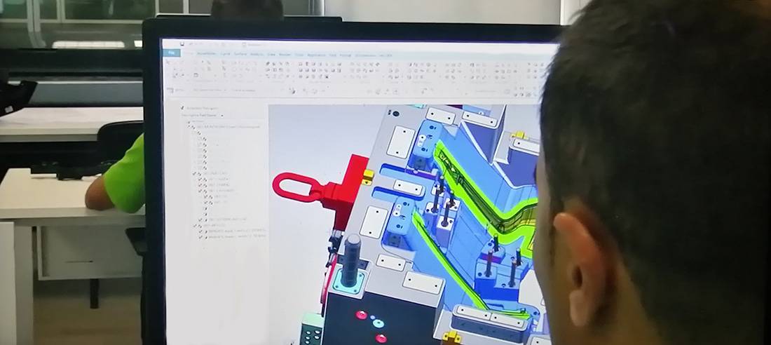
Why Partner with FMS for Mold Design?
FMS Mold Design combines decades of profound engineering expertise with state-of-the-art CAD technology to deliver high-precision tooling solutions. Supported by advanced data conversion tools and high-speed connectivity, our technical infrastructure makes global communication effortless and highly secure.
Real-Time Collaborative Engineering
We have redefined remote collaboration. Through our cloud-connected design workflows, your team can engage in real-time design reviews with our engineers at any time. We function precisely like an internal extension of your own design department—a high-touch approach that drives exceptional client satisfaction worldwide.
 FMS Mold Design Team delivers high-value, high-precision engineering solutions by seamlessly combining technical expertise with cost-effective execution. Our comprehensive services include mold feasibility studies, complete mold design and detailing, plastic part design and development, and advanced solid modeling.
Our Expertise & Capacity
The FMS engineering team consists of 10 dedicated designers, each bringing a minimum of 15 years of hands-on experience in mold design, manufacturing, and injection molding. All team members possess robust CAD/CAM/CAE competencies.
Our Design Director, David Zhang, leverages nearly 30 years of industry experience and a strong academic background in engineering. He possesses a profound understanding of European and American mold design and manufacturing standards (HASCO, DME, etc.). This deep integration of “real-world” manufacturing knowledge ensures every design we deliver is fully optimized for production, reducing lead times and costly modifications.
A Collaborative Partnership
We operate as a seamless extension of our clients’ internal engineering teams. Thanks to our diverse portfolio and decades of cross-industry experience, we adapt quickly to unique project requirements. We work closely with your engineers to deliver reliable, high-quality designs that strictly align with your standard operating procedures.
Value-Added Services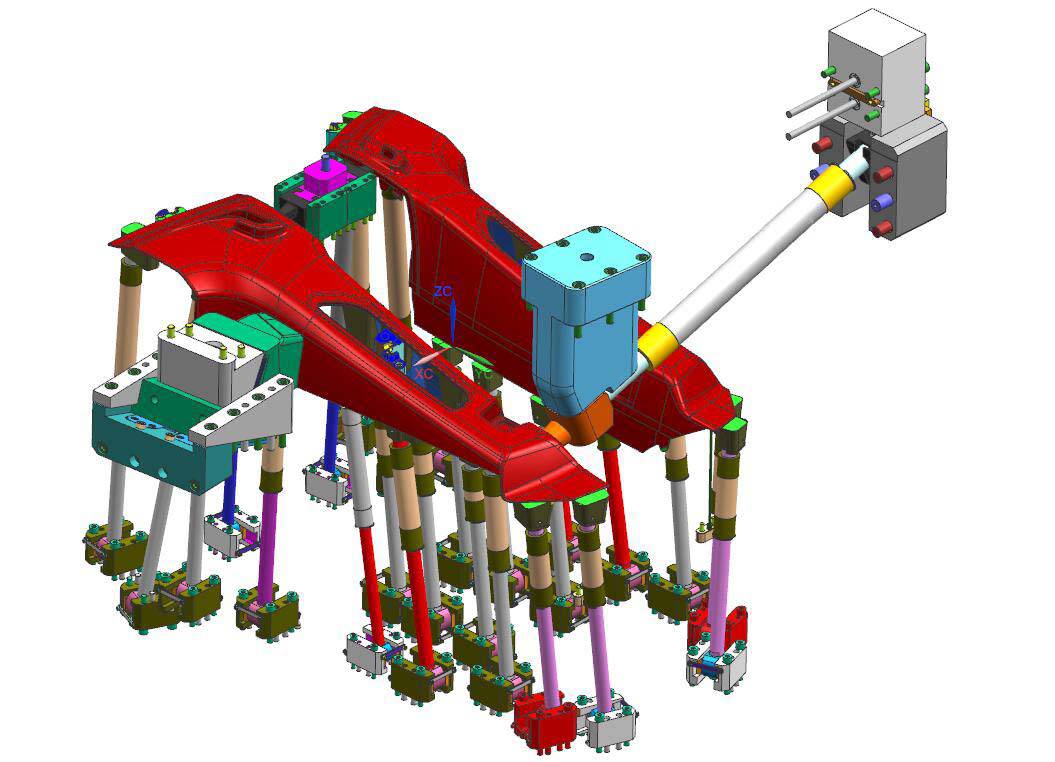
At FMS, our engineering team goes beyond standard mold design to deliver comprehensive, end-to-end technical support. Leveraging our deep industry expertise, we act as an extension of your team to provide specialized value-added services that optimize your production and fill internal capability gaps.
Our extended capabilities include:
Design for Manufacturing (DFM) and Mold Feasibility Studies / Offshore Mold Design and Third-Party Design Verification / On-Demand Engineering Resources (Additional Design Capacity)
Component Optimization Support (Assistance with Part Design) / Reverse Engineering
Design for manufacture /Mold Feasibility Studies / Designs for Off Shore Mold/Checking Designs / Additional Design Capacity /Assistance with Part Designs / Reverse Engineering
 Product Scope: Armed with a rich legacy in industrial design, our team delivers high-impact solutions across highly regulated and complex sectors. Our cross-industry footprint spans Medical Devices, Aerospace, Robotics, and Automotive, as well as Consumer Electronics, Smart Home Appliances, Workplace Technologies, and Commercial Toys. We seamlessly translate specialized technical requirements into market-ready product excellence.
Design & Engineering Flexibility
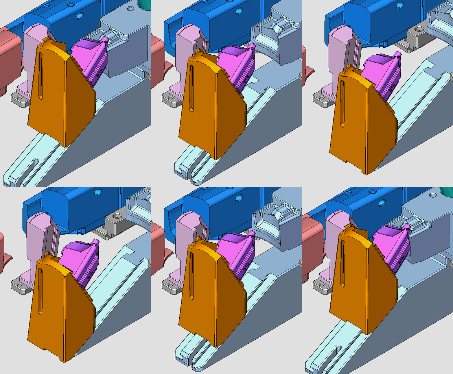
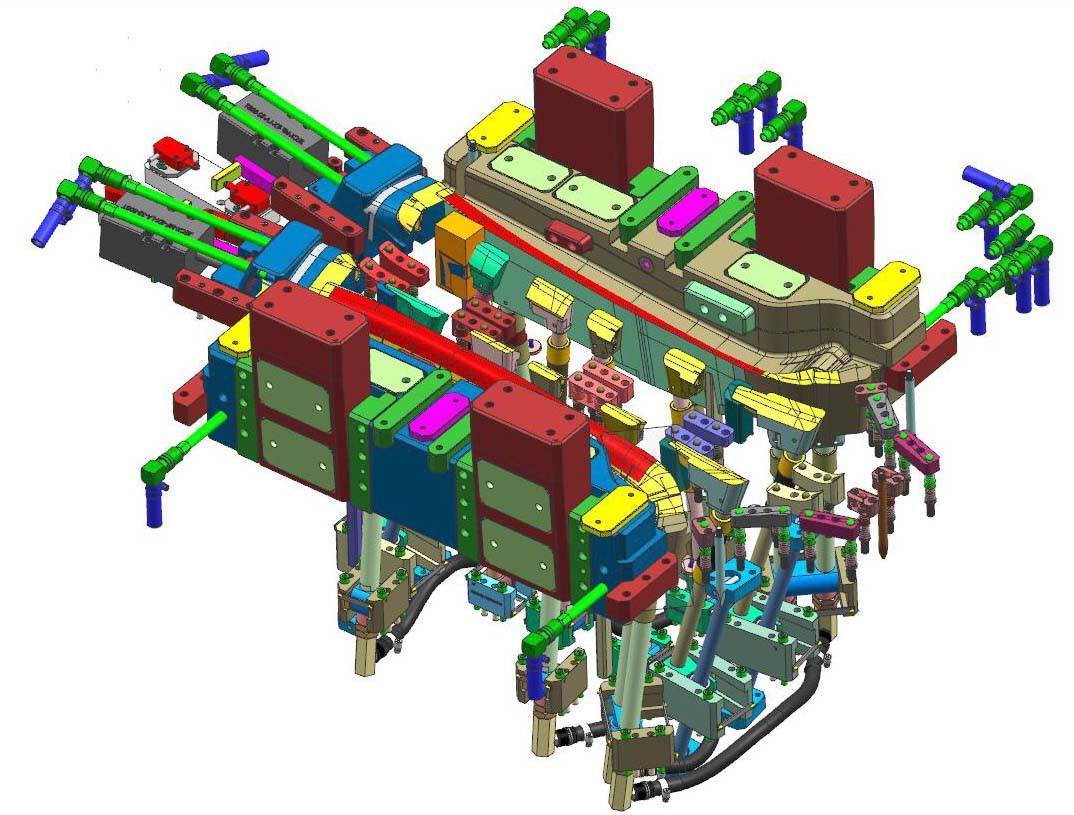
Every manufacturer operates on a unique ecosystem integrating mold design with production. At FMS, our engineering team seamlessly bridges design with advanced manufacturing methodologies. We provide fully customizable deliverables, ranging from 2D component drawings and CAD formats to precise 3D surfaces and comprehensive solid CAD data. Whether your project requires only a 2D assembly for rapid quoting or full solid CAD files with detailed hardware, cooling channels, and lifters, we adapt to your workflow. With robust data translation capabilities, we ensure seamless format compatibility—delivering exactly what you need, how you need it.
 Mold Design & Engineering Process
Robust mold design is the foundational element of a product’s manufacturing success. By engaging with our engineering team early in the design cycle, we help you optimize part geometry, mitigate manufacturing risks, and reduce overall tooling costs.
We understand that early-stage designs involve highly sensitive proprietary information. We treat your Intellectual Property (IP) with the strictest confidentiality, and we are fully prepared to execute a Non-Disclosure Agreement (NDA) before reviewing your concepts. Mutual trust is the cornerstone of our engineering partnerships.
Phase 1: RFQ & Initial Feasibility Assessment
To provide an accurate initial quotation and perform a preliminary Design for Manufacturing (DFM) review, we require the following baseline data:
• Product Geometry: Part drawings, 3D concept models, rough sketches, or physical prototypes.
• Application Environment: Product specifications, including mechanical performance requirements and operating conditions.
• Resin Specification: Intended base material (if predetermined).
• Production Volume: Estimated Annual Usage (EAU) and target production batch sizes to determine the appropriate tooling class (e.g., SPI Class 101 vs. Class 103).
During this phase, our engineering team collaborates with you to evaluate the part design for manufacturability, identifying opportunities to optimize cycle times, eliminate cosmetic defects, and minimize initial tooling investments.
Phase 2: Tooling Design & Engineering Validation
Upon successful acceptance of the quotation and project award, we require a comprehensive data package to initiate the formal mold design process:
• 2D Engineering Drawings: Fully dimensioned prints in .DWG or .DXF format.
• 3D CAD Data: Native CAD files or universal formats (.STEP, .IGES, or .X_T Parasolid).
• Material & Esthetics: Final confirmation of the raw material resin, grade, and color (Pantone/RAL or texture requirements).
• Critical-to-Quality (CTQ) Dimensions: A maximum of 5 key inspection measurements for quality control tracking.
• Project Governance: Designated primary engineering and commercial contacts for technical queries and milestone updates.
 How We Execute Mold Design
Our process begins by gathering all necessary project data to provide an accurate initial quotation. We then perform a comprehensive Design for Manufacturability (DFM) review to optimize the part for production and identify potential cost savings. Following this, we generate a detailed Mold Design Specification (MDS). This guide outlines all critical requirements, including tool specifications, design standards, steel types, standard components, resin selection, shrinkage allowances, and processing parameters.
This specification guide is shared across our design, project management, and production engineering teams to ensure absolute consistency from concept to final manufacturing. Throughout production, we enforce a strict quality control workflow to maintain seamless data integrity between our 3D design models and CNC programming.
Our Stage-Gate Mold Design Process:
1. Mold Specification & Requirement Definition
2. Preliminary Tool Schematic & Concept Layout
3. Schematic Review & Customer Approval
4. Full 3D CAD Design
5. Detailed 2D Engineering Drawings & Manufacturing Documentation
Injection molding is a popular manufacturing process for the mass production of identical plastic parts with good tolerances. During this process, thermoplastic flakes or pellets are melted down and injected into a mold. Once the thermoplastic material cools and hardens, ejector pins pop the completed part out from the mold.
Injection-molded parts can feature complex geometries, and offer product designers a fair amount of design flexibility. The only caveat is that product teams must design their parts around the specific requirements of injection molding.
It’s very challenging to make design adjustments after the part has already been manufactured. As such, product designers must design the plastic part perfectly for injection molding to reduce the risk of issues with the tool design, achieve the best results, and reduce costs.
Three injection mold design tips and best practices
Injection-molded parts can feature complex geometries, and offer product designers a fair amount of design flexibility. The only caveat is that product teams must design their parts around the specific requirements of injection molding.
It’s very challenging to make design adjustments after the part has already been manufactured. As such, product designers must design the plastic part perfectly for injection molding to reduce the risk of issues with the tool design, achieve the best results, and reduce costs. To design clean, functional parts, start with these three injection molding design best practices:
1. MAINTAIN CONSISTENT WALL THICKNESSES
The number one rule of injection molding part design is managing the thickness of the mold. Non-uniform walls can cause the part to warp as the thermoplastic material cools down or cause sink marks to occur. Recommended wall thicknesses vary depending on the plastic used. For example, polyurethane (PUR) has a recommended wall thickness of 0.080 inch to 0.750 inch, while polystyrene (PS) has a much smaller range of 0.035 inch to 0.150 inch. A good rule of thumb is to keep any given mold’s wall thickness between 1.2mm and 3mm.
2. ELIMINATE UNDERCUTS THAT AREN’T DESIGN CRITICAL
Undercuts are features that prevent the injection-molded part from being ejected cleanly from the mold without any structural damage. Undercuts can come in a variety of forms — holes, cavities, or areas where alignment is not perpendicular to the mold’s parting line. A product designer’s best bet is to avoid undercuts altogether. They always make the injection mold design more expensive, complicated, and labor-intensive than necessary.
Still, there are a few design tricks to handle undercuts. The simplest way to fix an undercut is to move the parting line of the mold such that it intersects with the undercut. However, this tip is only applicable for designs with undercuts on the outside of the mold.
3. DRAFT, DRAFT, DRAFT
Draft angles are design considerations that make it easier to cleanly eject an injection-molded part from the mold. This might sound like a non-essential design feature, but drafts are critical to manufacturing functional injection-molded parts. Drafts help prevent the part from becoming damaged upon release, lower production costs, accelerate production timelines, ensure a uniform surface finish, and provide a slew of other benefits. Without draft angles, product teams risk damaging their expensive molds and producing a large number of rejectable parts.
Even if it looks like draft might negatively impact the performance of the part, it’s always better to have draft than to not have draft. Parts can be designed with a minimum of 0.25 degrees of draft, generally, but the smallest degree of draft possible will depend on the part’s unique geometry and material.
Injection mold design tips
A good design must be practical. The mold maker must be able to produce the components in a logical, orderly manner to make money. Often, close tolerance dimensions are specified when a much looser tolerance could have easily done the job.
Take an ejector pin plate, for example. Everyone knows that the thickness is basically irrelevant, but usually the dimension given is a close tolerance size. An experienced toolmaker will just ignore the tolerance and proceed, but nowadays, with the specialization of tasks in the shop, a less skilled operator would waste precious time holding an unreasonable tolerance.
The 3D geometry must be clean. The fast pace of mold making today makes it essential to have efficient, reliable software. The days of vague sketches, or toolmakers making up the design as they go are long gone. There are many excellent companies that offer high end software programs for designing molds, dies, and just about any kind of tooling you can imagine.
CNC machines need clean geometry to run properly. If the design is sloppy and the translation of different software messy, the end result will show it. Plus, the operator will have a much easier time running the programs with clean geometry.
The design must be clear in it’s function. It is maddening for a plastic injection mold maker to spend hours deciphering what the designer means. Information that is assumed or omitted can delay the construction by days and cause unnecessary errors. Why should a toolmaker spend time looking up information that was right in front of the designer at one time?
It is always much easier to include notes or details that show what is required than to search it out later on. Once the design is in process, and the information is available, why not simply give the mold maker the same information? For example, a 3D drawing can visually clarify many questions.
At the risk of sounding like a broken record, the length of time it takes to make an injection mold all depends on the component design. The more features on the component requiring the mold to deviate from a straight pull design, the longer its design, fabrication, and build will take.
Every mold starts from the concept, can the part can be formed simply by pulling the two halves of the mold apart? That is know as a “straight pull” mold. Then you start adding in component features like undercuts and threads, which add features to the mold like hydraulics and slides making the mold more complex and adding to its development time.
Part geometry that make the part more difficult to separate from the two halves and added ejection components to get the part out of the mold also add to the mold’s complexity, cost and timeline.
Suffice it to say, a mold build of varying complexity can take as little as two weeks to as many as 12 weeks.
Do you want to cut down the time it takes for mold completion? Sit down with your mold designer and molder EARLY and often. Let them help you to accomplish the design requirements you have but make the part easier to accommodate a mold and easier to injection mold. Do that and you can win the trifecta in time to market, development cost AND production standard cost.
Injection mold design tips
A good design must be practical. The mold maker must be able to produce the components in a logical, orderly manner to make money. Often, close tolerance dimensions are specified when a much looser tolerance could have easily done the job.
Take an ejector pin plate, for example. Everyone knows that the thickness is basically irrelevant, but usually the dimension given is a close tolerance size. An experienced toolmaker will just ignore the tolerance and proceed, but nowadays, with the specialization of tasks in the shop, a less skilled operator would waste precious time holding an unreasonable tolerance.
The 3D geometry must be clean. The fast pace of mold making today makes it essential to have efficient, reliable software. The days of vague sketches, or toolmakers making up the design as they go are long gone. There are many excellent companies that offer high end software programs for designing molds, dies, and just about any kind of tooling you can imagine.
CNC machines need clean geometry to run properly. If the design is sloppy and the translation of different software messy, the end result will show it. Plus, the operator will have a much easier time running the programs with clean geometry.
The design must be clear in it’s function. It is maddening for a plastic injection mold maker to spend hours deciphering what the designer means. Information that is assumed or omitted can delay the construction by days and cause unnecessary errors. Why should a toolmaker spend time looking up information that was right in front of the designer at one time?
It is always much easier to include notes or details that show what is required than to search it out later on. Once the design is in process, and the information is available, why not simply give the mold maker the same information? For example, a 3D drawing can visually clarify many questions.
In the future mold industry, mold design will become more and more important, especially 3D mold design
There are thousands of designers who design injection molded parts but there is an elite group within this large community who can actually design parts for injection molders. Injection molded product design evolves through many phases of development before all the parts are ultimately documented and released to a molder for production. This last step in the development process is the most critical, since design changes or corrections can no longer be made without significantly adding cost or project delays.Unfortunately, plastic part design mistakes will be uncovered only after first article parts are inspected and evaluated by the project team. Even with today’s sophisticated mold flow simulation, 3D CAD interference checks, rapid prototyping and numerous other development tools, it is impossible for anyone to predict every potential problem for an injection molded part. However, there is a very simple, low-cost method for minimizing potential problems and virtually ensuring perfect parts. It’s called partnering with your molder.
it should be noted that designing a quality injection molded part requires a designer to be knowledgeable about all the fundamental design parameters associated with injection molding and to be highly skilled in the art. The molder/designer partnership is not intended to be an internship program—it is supposed to optimize handoff of the final design to production with few or no changes. If completed successfully, final production parts typically are cost effectively molded precisely to specifications.
One of the greatest challenges for any designer faced with designing an injection molded part is providing enough clearance in the design for tolerance variation. Tolerance variation depends upon several variables, including materials, process control and tool design. Acceptable tolerance ranges in a design will vary greatly from one molder to another. It’s imperative that designers discuss reasonable critical tolerance specifications with a molder and consider options for possible mold revisions, if required. This may require certain design features to be intentionally designed with extra clearance, which will later be tightened by removing steel from the mold. No one wants to add steel with welding to remedy interference problems. Molders may offer a number of suggestions for maintaining tight tolerance control, including post machining, fixturing and gate locations.
we want mold desgiening services
Please send the product design data and mold technical requirements to [email protected]. Our relevant person in charge will contact you as soon as possible. thanks!
The importance of mold design on the productivity of a tool is often overlooked in the design of a mold. Several areas in the mold design exist where the molder must work with the mold builder in order to optimize the productivity of the mold. A good standard for mold productivity is saleable parts out of the press per hour. Cycle time and part quality are the critical aspects of saleable parts per hour. The areas of design found to be most important for increased productivity are the sprue bushing, runners and gates, hot manifold, venting, cooling, and ejection. While each of these items is specific to the mold being built, good design for each can contribute to improved part quality and optimum cycle time.