
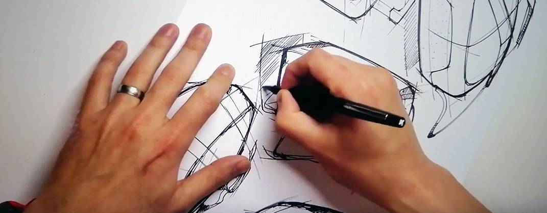
The Importance Of Product Design
Product design is the cornerstone of successful manufacturing. In fact, product molds represent nearly 40% of the entire molding industry, underscoring just how critical the design phase is to a product’s ultimate success. However, bringing a concept to life requires adherence to strict engineering rules and highly specialized expertise. It demands professionals.
Backed by decades of manufacturing excellence, the FMS Design Team transforms your concepts into market-ready realities. We don’t just design; we optimize your products for scalability, cost-efficiency, and premium quality.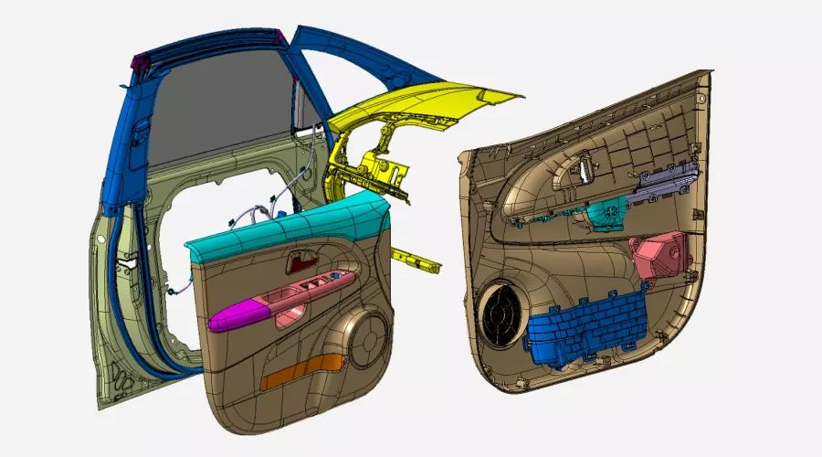
Seamless Collaborative Design
We have broken down geographic barriers with our advanced Internet-enabled Collaborative Design system. Distance is no longer a factor. You can review designs, analyze structures, and assemble virtual prototypes alongside our engineers in real time.  It feels exactly like having an in-house design department right next door—a seamless partnership that consistently earns the highest satisfaction ratings from our global clients.
Why Choose FMS for Product Design?
At FMS, we bridge the gap between innovative concept and flawless production. Here is how our unique design advantages accelerate your success:
• Design Built for Manufacturing (DFM): Backed by extensive expertise in molding simulation analysis and advanced mold design, our team ensures your products are optimized for production from day one—minimizing errors and reducing time-to-market.
• Strategic Global Hub Advantage: Located at the absolute epicenter of the world’s mold-making and molding industry, we have direct access to cutting-edge techniques and top-tier manufacturers. This keeps our designs at the forefront of global innovation.
• Premium Quality, Competitive Edge: We deliver professional, efficient, and high-integrity design services that meet strict Western quality standards—offering you premium engineering expertise at a highly competitive price point.
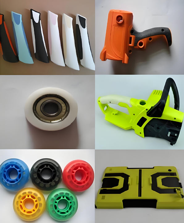
Elevate Your Product with High-Impact Design
Great design shouldn’t cost more. We transform standard product concepts into eye-catching, market-ready products that consumers actually want to buy—without driving up production costs.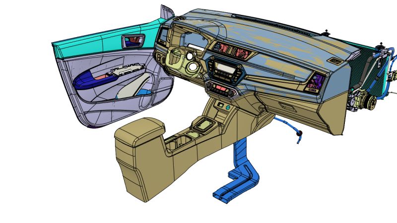
Utilizing industry-leading CAD systems, our team combines advanced surface modeling expertise with a deep understanding of economical injection molding. But we provide more than just technical tools. We bring the artistic vision and stylistic intuition needed to give your product a competitive edge. Let us help you turn your next big idea into a beautifully engineered, commercial success.
Maximizing Performance Through Design for Manufacturing (DFM)
Designing parts with advanced materials requires a unique mindset: they must be strictly engineered for seamless production. While basic product design is common, achieving true excellence demands deep expertise in manufacturing processes and tooling functionality.
With a proven track record in world-class mold design, we possess an unmatched understanding of tooling and molding dynamics. By combining this hands-on manufacturing insight with our advanced CAD and FEA stress analysis capabilities, we deliver optimized, production-ready designs that elevate your product’s performance from day one.
Why Stress Analysis is Critical for Plastic Design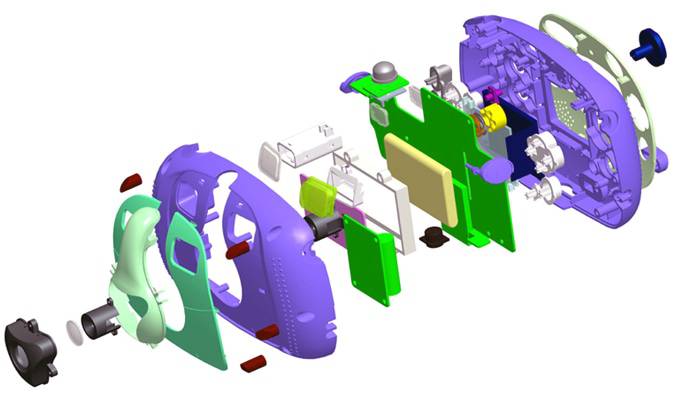
 It is well established that the structural characteristics of plastics differ fundamentally from those of metals. However, even a foundational concept like “stress” takes on a completely different meaning when applied to a plastic component versus a metal one. The core challenge for engineers is understanding exactly how these divergent material properties impact the design process.
While plastics are often perceived as a low-cost material, they are actually quite expensive from a unit-volume or load-bearing perspective. Their true cost-efficiency stems from the high-speed injection molding process. Given this reality, a 100% plastic design isn’t always the most cost-effective solution.
Furthermore, while plastics excel at handling intermittent loads, they are prone to permanent deformation (creep) even under low, long-term stress. In many designs, simply adding more plastic is not a viable fix. Instead, strategically integrating a small amount of load-bearing metal components into a primary plastic structure often yields a significantly superior, high-performance product.
What is Plastic Product Design?
It is the art of creating functional and aesthetically pleasing products made primarily or entirely from plastic materials. It involves designing products that not only serve their intended purpose but are also ergonomically sound, sustainable, and manufacturable.
Materials Matter
Choosing the right plastic material is fundamental to successful product design. Plastics vary in properties, from rigid to flexible, transparent to opaque, and durable to biodegradable. Understanding these materials’ characteristics is essential to match them with your design requirements.
Design for Manufacturability
Designing for manufacturability is a core principle. The design should take into account the capabilities and limitations of the manufacturing processes, such as injection molding, extrusion, or thermoforming.
Actually, we can simplify the plastic product design process into some steps:
1: Defining requirements
2: Create a preliminary concept sketch
3: Initial materials selection
4: Design part in accordance with material properties
5: structural analysis
6: Final materials selection
7: Modify the design for manufacturing (DFM)
8: Prototyping
9: Tooling
10: Production
Plastic part design geometry is one of the most important components in the design process. It affects not only the aesthetics but also the part’s performance, strength, and durability. So if you’re designing a plastic part, here are five key geometry tips that will help ensure its success:
Always define the part features’ design intent.
Ensure that your design intent is clearly documented, so everyone involved in the project understands it.
Define the part’s design requirements those things which must be true about the part of the product to make it work correctly.
Define any constraints on how a feature can be designed, e.g., limitations on manufacturing processes or materials used in production. Some constraints may be imposed by external forces outside your control. For example, regulations imposed by safety officials or material availability.
Ensure that you understand all of these requirements and constraints before proceeding with designing any features for a plastic part.
Build a draft angle into the part.
Draft angles are used to increase the strength of parts, reduce stress, and make it easier to remove a part from its mold.
A draft angle is the angle of a wall on a part as it transitions into another surface. The draft angle is also known as an undercut or negative draft angle.
Add ribs and gussets for added strength and durability.
Ribs and gussets are used to increase the strength and durability of a plastic part design. They can also be added to increase stiffness. This is important in parts needing to be stiff enough to withstand loads coming from their intended use. The placement of ribs and gussets must be carefully considered because they affect other aspects of the part’s design:
The thickness of ribs will determine the amount of material used in areas where ribs are not needed or have been removed.
If you plan on printing your part on a 3D printer, then ribs should not be placed over areas where internal supports will be printed, as this could cause problems with printing accuracy if it causes issues with support removal later on down the line
The wall thickness should be uniform throughout the entire part.
One of the most important rules when designing a plastic part is ensuring its wall thickness is uniform throughout. This can be very difficult if you’re trying to model something with complex proportions, like an intricate shape or an irregular surface. However, all parts must have the same wall thickness, so they don’t crack during production or in use.
The recommended minimum wall thickness for any given material is determined by three factors: 1) The desired strength of the part; 2) The amount of plastic needed for production; 3) The length/width ratio of your design (i.e., whether it has a lot more surface area than depth/thickness).
Place threads in cavity walls to reduce stress concentrations.
It’s important to place threads in cavity walls to reduce stress concentrations. Stress concentrations are points where the stress is high, and if you have a part with many of these points, it can be difficult for the part to handle the stresses without breaking. Threads are one way to get around this issue.
Threads can be used at the top and bottom of the cavity wall where no other loads are applied directly on them (usually at least two millimeters away from any other load-bearing surfaces). The distance from a threaded hole or pinhole should be equal in all directions: i.e., if you put it 1 mm from one edge and 2 mm from another edge, you should put it 3 mm from an adjacent surface so that they are equidistant from each other.
Injection-molded plastic part design is a lot like parenting.
The job falls into your lap, you have zero qualifications, and yet, you are supposed to do it perfectly while blindfolded. It’s difficult to lunge forward with confidence when you are building on a poor foundation.
The result is that you proceed with the project with a “learn-as-you-go” approach. Even so, there’s still opportunity to avoid common mistakes, make smart decisions, and release a smart, young, well-prepared injection-molded part into the universe, ready to make a big impact and change the world.
There are engineering schools that offer an exclusive plastics track, but they aren’t numerous. Furthermore, a “track,” is an optional route at the tail end of your curriculum as opposed to a core/required course. Most engineering schools address plastics in material science classes, but this aims to understand materials at a microscopic level — learning their bonding structure, and the behavior you can expect from a part made of plastic.
There are two important components of plastic part design that are absent in most engineering curricula: mold design and plastic part design. Mold design includes the part cavity, run time, gate diameter, cooling channels, cycle time, and the general mechanics of manufacturing a plastic part.
The other missing component is plastic part design — understanding the form that part must assume for proper manufacturing.
To clarify: I’m not criticizing the schools, just identifying a void. There’s simply so much engineering theory to cover in four years, and students are simply hoping to get through engineering school with some breath still left in them.
Moving on to industry, upper management is blind to this void. They aren’t approaching each designer and questioning our knowledge of our craft. They are making the assumption that, “Yes, you are an engineer, and obviously this task, plastic part design, lands in your territory. You know how to do this.”
There are four key sources for learning plastic part design, listed here in order of increasing impact:
Networking with other engineers
Touring an injection molding facility (local and overseas)
Talking to a toolmaker
Looking at “bad” parts (design flaws)
I’ve learned the most from bad parts. I’ll share– some design tips with you that are fundamentals, and I’ll also share some tips on how to enhance the product beyond simply function and form.
Furthermore, you’ll find that the best/smartest designs are all around (your desk and chair even), so look for inspiration. My favorite plastic design right now is the Cuisinart ice cream maker. It’s a reminder that the things we engineer should be smart, simplified, and easy to use/operate.
Perhaps you aren’t designing a consumer product.
The real message is that the smartest designs are actually very simple and have creative features to get the job done. Don’t look only to other plastic designs. You can apply all of your knowledge about things you already know, such as sheet metal. A lot of the principles can be applied in plastics.
Whenever you begin a design project involving plastic parts, where your end goal is to have the component injection molded, you’ll want to consider some things on the front end of your design process that will allow for time and money to be saved during the production phase of your project. This foresight at the beginning stages of product design will be useful in understanding the limitations and challenges faced by the manufacturers of your product.
These 10 considerations are by no means exhaustive when considering the best plastic injected part design, but they will for sure get you very close to where you need to be and at the very least, point you in the right direction. So let’s check out these helpful tips:
1. Consider the Parting Line
Try and imagine your part being molded. It can be difficult for some to think in the “negative”, and by that I mean visualizing the empty cavity space that the liquid plastic will fill in order to mold into a plastic part. Inevitably, once that cavity space is filled, your part will have to be ejected from that space. In order for that to happen, the two mold halves will have to separate, leaving behind your plastic injected part in one side of the mold (preferably the side where you plan on ejecting from). You need to visualize and plan for where this “parting line” will be so as to ensure that your part does not get trapped in the mold.
2. Avoid Undercuts (If Possible)
Undercuts on your part wont necessarily make it more difficult to mold your part, but rather more difficult to demold. The undercut portion of the plastic part will get trapped inside your mold once the part is cooled and hardened, and in turn making it impossible to eject from the mold without other mold actions. Many times, undercuts are a necessity for part function. Side actions and lifting mechanisms will have to be introduced to your tool in order to deal with the ejection of your part. Sometimes this is not avoidable, but if you are looking to save on tooling cost, it might be worth trying to redesign in order to eliminate necessary tooling costs.
3. Uniform Wall Thickness
You want to make sure that you try and make the wall thickness of your part as consistent as possible. It’s alright if you don’t have uniform wall thickness to some extent, but uneven wall thickness greatly increases the likelihood of sink marks, warpage, voids, molded-in stress, longer cooling times, and even material flow restrictions. If wall thickness must be uneven, it is best to have smooth transitions that taper over some distance. The size of the part and the ability of the material to fill will determine the minimum wall thickness allowed for your plastic injected part.
4. Shrinkage and Warpage Considerations
All materials shrink at different rates and at varying degrees within the cooling process of your injection molding operation. Shrinkage and warpage are two different phenomena that can occur. Shrinkage occurs where there is a difference between corresponding linear dimension of the mold and the molded part. Warpage is a dimensional distortion in a molded plastic caused by excessive residual stress in the part. There are various things to consider when trying to control either one of these occurrences. Material considerations, part geometry considerations, tooling considerations, and processing considerations all play a part.
5. Watch The Sharp Corners
Sharp corner are to be avoided at all costs. Sharp edges, such as corners of a square hole, will produce a part with high levels of molded-in stresses. These much of the time result in weak points that lead to part failure and cracking. Adding radii to sharp corners will reduce the amount of molded-in stress. Radii redistributes the stress more evenly and facilitates the flow of the material and ejection from the mold. Stresses rapidly build whenever the inside corner id less than 25% of the nominal wall thickness of the part.
6. Structural Support
As a product designer you want to minimize the amount of material required to fill your part, while at the same time increasing its structural integrity. Thin walls need some sort of support so that the walls don’t warp or collapse. Ribs are commonly employed on injection molded parts in order to stiffen relatively thin parts. Ribs, bosses and other projections on the piece part wall will greatly strengthen your part while, but if done incorrectly can contribute to other molding issues such as sink marks and non-fills.
7. Add Draft
Draft is the angling of otherwise vertical walls in order to prevent constant contact with the molding cavity during the mold opening. All vertical walls oriented normal to the direction of mold pull will need to have draft ideally at 1 degree minimum. There are special consideration for ribs and bosses, and textured surfaces will need to add 1 degree per side for each .001″ depth of te
Design for manufacturability (DFM) is the general practice of designing parts so that they are also efficient to produce. While specific best practices vary by manufacturing technology, the ultimate goal of DFM in general is to optimize part design so as to minimize the manufacturing costs — without sacrificing on performance or function. DFM also helps you identify potential issues or defects early and avoid disruptive re-designs down the line, which is why assessing possible manufacturing methods is crucial during the initial design and prototyping phases.
Intentional, method-focused design is especially important when attempting to produce parts with complex geometries or intricate features. And while there are many viable manufacturing methods for producing parts with complex geometries, injection molding is among the most common.
DFM is especially important for injection-molded parts, as the hard tooling and molds used to create injection-molded parts introduce a number of variables that may impact design — including mold temperature, material temperature, and air pressure. What’s more, injection molds are expensive and time-consuming to tool, and the process typically only becomes cost effective when producing parts in high volumes, so consistency and repeatability are critical when designing parts with complex geometries or intricate features.
Here are 5 key tips for how to design plastic injection molded parts with complex features.
1. Take advantage of sliding shutoffs for clips and snap fits
Clips and snap fits are two forms of fastening mechanisms that can be incorporated directly into the injection mold design — a few common examples being tool set lids and electronics housings. Both operate similarly: on one side of the mechanism, a flexible tab of material catches on a slot or pocket in the mating part, thereby securing the two.
Sliding or telescoping shutoffs are components machined into one side of the mold that extend into the other half, sliding into place when the mold is closed. This prevents material from flowing into particular areas, which makes it possible to easily incorporate features like hooks and holes (including long through-holes) without the need for expensive side actions, bumpoffs, inserts, and other features that increase the cost and complexity of the mold design.
Sliding shutoffs can be designed to have the same tab and slot to match the part’s clips and snap fits, creating features that fit together securely and retain enough flexibility to pull apart without breaking. Shutoffs can reduce mold design and operating costs and also generally be used as a workaround for undercuts and recessed features.
In general, both the part and mold should have a minimum of 3 degrees of draft to prevent metal from rubbing against metal, which can create flash and damage the shutoff.
2. Choose the right material for living hinges
Living hinges, another flexible lid feature, are an excellent way to attach the two halves of injection molded plastic components (think of the lids on the individual containers of a weekly vitamin dispenser, for instance).
While material consideration is always a critical consideration in design and product development, it should be your primary concern when designing living hinges. Polypropylene, for instance, is better-suited for this feature than polycarbonate (which can be an excellent material for clips and snap fits). Depending on the range of motion that’s expected of the lid, you may need to incorporate a radius at the hinge’s midpoint to allow the two parts to close more easily.
3. Keep an eye on wall thickness
Wall thickness should remain uniform whenever possible, as variations in thickness can introduce serious complications. Parts with non-consistent wall thickness are at risk of warping (caused by different sections of the part cooling at different rates, which creates internal stress that bends the part permanently).
Variations in wall thickness, like this example, can lead to sink marks, voids, and warping.
Furthermore, if the walls of a part are overly thick or thin, further issues may arise. For example, thin walls and poorly designed support ribs can impede flowability, causing short shorts (or incomplete mold fills). On the other hand, parts with thick walls and poorly designed ribs are prone to developing sink marks, or impressions on the surface of the part caused by the interior resin cooling faster than the exterior material. If you see signs of either flaw, it might be time to reexamine your mold design.
4. Add draft and reduce the height of tall features
Tall features like bosses, ribs, and standoffs may require you to incorporate greater draft angles (generally up to 3°) to ensure the part leaves the mold without drag lines or other ejection issues. Bosses and tall features allow for threaded inserts and additional part strength, but they increase the risk of developing sink marks.
Furthermore, increasing the height of ribs and other features likewise increases the depth of the mold, increasing the need for longer end mills, more venting, and slower cutting rates during the machining process. One way to work around this is to support bosses with peripheral vertical ribs, which have thinner walls, reducing the chance of sinks.
FR Injection Molding drafts2Long Description
Angled bosses and other features increase the complexity of production, as the axis of the boss no longer aligns with the parting line or the line of pull — which all but necessitates that an insert will need to be manually loaded into the mold before each shot.
5. Be strategic about text and logos
Text (such a product or company name) or logos are commonly added to injection molded products. The good news is that small font sizes are actually fairly easy to achieve through injection molding — so long as you follow a few key guidelines.
First, text should be a sans-serif font and the shortest stroke length (the crossbar of a T or a A, for example) must be at least 0.020” in length. Raised text is easier to read and to produce than text sunk into a part’s surface. Unless the text is inordinately large, it should not be more than 0.015” tall.
Injection molded plastic parts have some wonderful benefits including scalability, the ability to make simple to extremely complex parts, and uniformity, the ability to make hundreds to millions of virtually identical parts. However, the building and maintaining of injection mold tools can be expensive and making tool changes can be challenging.
Whatever the project, industrial designers, engineers and product designers may face some challenges when designing for injection molding. The following details three mistakes designers should avoid for successful injection molded parts.
Non-Uniform Walls
On average, the minimum wall thickness of an injection molded part ranges from 2mm to 4mm (.080 inch to .160 inch). Parts with uniform walls thickness allow the mold cavity to fill more precisely since the molten plastic does not have to be forced through varying restrictions as it fills.
If the walls are not uniform, the thinner sections cool first. As the thicker sections cool and shrink, stresses occur between the boundaries of the thin and thick walls. The thin section doesn’t yield to the stress because the thin section has already hardened. As the thick sections yields, warping and twisting of the part occurs, which can cause cracks.
If design limitations make it impossible to have uniform wall thicknesses, the change in thickness should be as gradual as possible. Coring is a helpful method where plastic is removed from the thick area, which helps to keep wall sections uniform. Gussets support structures can also be designed into the part to reduce the possibility of warping.
Not Utilizing Draft
Mold drafts facilitate part removal from the mold. The draft must be in an offset angle that is parallel to the mold opening and closing. The ideal draft angle for a given part depends on the depth of the part in the mold and its required end-use function.
Allowing for as much draft as possible will permit parts to release from the mold easily. Typically, one to two degrees of drafts with an additional 1.5 degrees per 0.25mm depth of texture is sufficient.The mold part line will need to be located in a way that splits the draft in order to minimize it.
Sharp Corners
Sharp corners greatly increase stress concentration, which, when high enough, can lead to part failure. Sharp corners often come about in non-obvious places, such as a boss attached to a surface, or a strengthening rib.
The radii of sharp corners needs to be watched closely because stress concentration varies with radius for a given thickness. The stress concentration factor is high for R/T values, less than 0.5, but for R/T values over 0.5 the concentration lowers. It is recommended that an inside radius be a minimum of 1 times the thickness.
In addition to reducing stresses, the fillet radius provides a streamlined flow path for the molten plastic, resulting in an easier fill of the mold. At corners, the suggested inside radius is 0.5 times the material thickness and the outside radius is 1.5 times the material thickness. A bigger radius should be used if part design allows.
Plastic parts can be designed in many different varieties. But these all share the same basic principles that make a big difference with your final product. Understanding some of these can save your project a lot of time and effort.
Use an experienced Plastic Injection Moulding provider
It might seem like an obvious point, but an experienced plastic injection molding operator will help you avoid many classic mistakes made with part designs. A simple example is the placements of the gates – this is where the molten plastic will be injected into the mold. How the plastic flows and cools determines many of the properties of the part, such as seams and weak spots. Experience can dictate the best designs for your mold that will also compliment the process you wish to use.
Plastic objects need to cool before they come out of the mold, which will result in slight shrinkage. Ideally, the product should slide out easily. But if the sides are completely straight, this is far less likely to happen and you may have to force the part out, risking damage to the part as it scrapes due to friction. Adding a very slight taper to the external sides of the part fixes this problem. It’s a very simple idea, yet hugely effective and a fundamental principle of injection molding design.
Sink marks, which is where flat surfaces instead curve inwards – as if the plastic wall as sunken in – is a common problem with plastic molding. This happens because the different areas in the part didn’t cool uniformly. It’s mainly a question of space and time: areas that need more plastic will take longer to fill and cool, raising the risk that they will deform as the rest of the part cools faster. The way to avoid this is to try and keep the main walls’ thicknesses as uniform as possible.
Avoid hard corners
As molten plastic moves into the mold, it will attempt to fill every nook and cranny. But hard and sharp corners are much more difficult to fill. This can cause turbulence in that area, leading to poor fills and other shape problems. Professional designers thus prefer to use slightly rounded corners: these help the plastic flow more comfortably into the corner, filling it uniformly.
Know your materials
Know what type of plastic you want to use or what your options are. Different plastics have different properties, such as their viscosity (how well they flow when heated) and their cooling rate. This can be further altered by additives. The material you use will have a lot to do with the purpose of the part – for example, you may want UV resistance. Bt this can impact other properties and how the plastic responds to different designs. It is quite possible to have a mold made that will not work with the intended material, so do your homework to ensure you get a happy harmony.
The product design process is a vital stage in the production of any product. We work with independent Product Design agencies that don’t just work within the Plastics industry, but they are able to design for manufacture in any material that is right for your project. Therefore, if your project requires multiple materials, metals, electronics etc, this can all be catered for.
We use this independent route instead of having our own in-house designers as we feel this gives our clients the best possible options for their products and components, rather that purely designing for plastic injection moulding.
Hi Looney, good idea! maybe we can work together :-)