
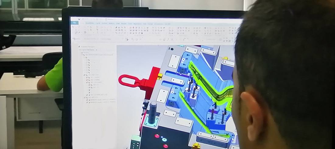
Why Partner with FMS for Mold Design?
FMS Mold Design combines decades of profound engineering expertise with state-of-the-art CAD technology to deliver high-precision tooling solutions. Supported by advanced data conversion tools and high-speed connectivity, our technical infrastructure makes global communication effortless and highly secure.
Real-Time Collaborative Engineering
We have redefined remote collaboration. Through our cloud-connected design workflows, your team can engage in real-time design reviews with our engineers at any time. We function precisely like an internal extension of your own design department—a high-touch approach that drives exceptional client satisfaction worldwide.
 FMS Mold Design Team delivers high-value, high-precision engineering solutions by seamlessly combining technical expertise with cost-effective execution. Our comprehensive services include mold feasibility studies, complete mold design and detailing, plastic part design and development, and advanced solid modeling.
Our Expertise & Capacity
The FMS engineering team consists of 10 dedicated designers, each bringing a minimum of 15 years of hands-on experience in mold design, manufacturing, and injection molding. All team members possess robust CAD/CAM/CAE competencies.
Our Design Director, David Zhang, leverages nearly 30 years of industry experience and a strong academic background in engineering. He possesses a profound understanding of European and American mold design and manufacturing standards (HASCO, DME, etc.). This deep integration of “real-world” manufacturing knowledge ensures every design we deliver is fully optimized for production, reducing lead times and costly modifications.
A Collaborative Partnership
We operate as a seamless extension of our clients’ internal engineering teams. Thanks to our diverse portfolio and decades of cross-industry experience, we adapt quickly to unique project requirements. We work closely with your engineers to deliver reliable, high-quality designs that strictly align with your standard operating procedures.
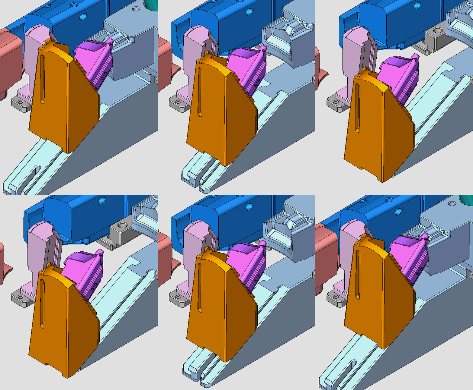
Value-Added Services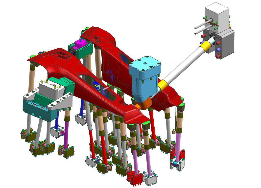
At FMS, our engineering team goes beyond standard mold design to deliver comprehensive, end-to-end technical support. Leveraging our deep industry expertise, we act as an extension of your team to provide specialized value-added services that optimize your production and fill internal capability gaps.
Our extended capabilities include:
Design for Manufacturing (DFM) and Mold Feasibility Studies / Offshore Mold Design and Third-Party Design Verification / On-Demand Engineering Resources (Additional Design Capacity)
Component Optimization Support (Assistance with Part Design) / Reverse Engineering
Design for manufacture /Mold Feasibility Studies / Designs for Off Shore Mold/Checking Designs / Additional Design Capacity /Assistance with Part Designs / Reverse Engineering
 Product Scope: Armed with a rich legacy in industrial design, our team delivers high-impact solutions across highly regulated and complex sectors. Our cross-industry footprint spans Medical Devices, Aerospace, Robotics, and Automotive, as well as Consumer Electronics, Smart Home Appliances, Workplace Technologies, and Commercial Toys. We seamlessly translate specialized technical requirements into market-ready product excellence.
Design & Engineering Flexibility
Every manufacturer operates on a unique ecosystem integrating mold design with production. At FMS, our engineering team seamlessly bridges design with advanced manufacturing methodologies. We provide fully customizable deliverables, ranging from 2D component drawings and CAD formats to precise 3D surfaces and comprehensive solid CAD data. Whether your project requires only a 2D assembly for rapid quoting or full solid CAD files with detailed hardware, cooling channels, and lifters, we adapt to your workflow. With robust data translation capabilities, we ensure seamless format compatibility—delivering exactly what you need, how you need it.
 Mold Design & Engineering Process
Robust mold design is the foundational element of a product’s manufacturing success. By engaging with our engineering team early in the design cycle, we help you optimize part geometry, mitigate manufacturing risks, and reduce overall tooling costs.
We understand that early-stage designs involve highly sensitive proprietary information. We treat your Intellectual Property (IP) with the strictest confidentiality, and we are fully prepared to execute a Non-Disclosure Agreement (NDA) before reviewing your concepts. Mutual trust is the cornerstone of our engineering partnerships.
Phase 1: RFQ & Initial Feasibility Assessment
To provide an accurate initial quotation and perform a preliminary Design for Manufacturing (DFM) review, we require the following baseline data:
• Product Geometry: Part drawings, 3D concept models, rough sketches, or physical prototypes.
• Application Environment: Product specifications, including mechanical performance requirements and operating conditions.
• Resin Specification: Intended base material (if predetermined).
• Production Volume: Estimated Annual Usage (EAU) and target production batch sizes to determine the appropriate tooling class (e.g., SPI Class 101 vs. Class 103).
During this phase, our engineering team collaborates with you to evaluate the part design for manufacturability, identifying opportunities to optimize cycle times, eliminate cosmetic defects, and minimize initial tooling investments.
Phase 2: Tooling Design & Engineering Validation
Upon successful acceptance of the quotation and project award, we require a comprehensive data package to initiate the formal mold design process:
• 2D Engineering Drawings: Fully dimensioned prints in .DWG or .DXF format.
• 3D CAD Data: Native CAD files or universal formats (.STEP, .IGES, or .X_T Parasolid).
• Material & Esthetics: Final confirmation of the raw material resin, grade, and color (Pantone/RAL or texture requirements).
• Critical-to-Quality (CTQ) Dimensions: A maximum of 5 key inspection measurements for quality control tracking.
• Project Governance: Designated primary engineering and commercial contacts for technical queries and milestone updates.
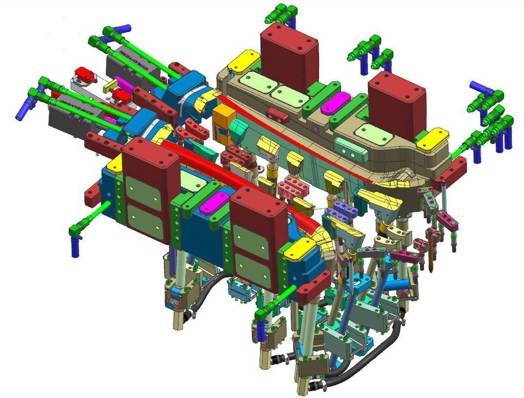 How We Execute Mold Design
Our process begins by gathering all necessary project data to provide an accurate initial quotation. We then perform a comprehensive Design for Manufacturability (DFM) review to optimize the part for production and identify potential cost savings. Following this, we generate a detailed Mold Design Specification (MDS). This guide outlines all critical requirements, including tool specifications, design standards, steel types, standard components, resin selection, shrinkage allowances, and processing parameters.
This specification guide is shared across our design, project management, and production engineering teams to ensure absolute consistency from concept to final manufacturing. Throughout production, we enforce a strict quality control workflow to maintain seamless data integrity between our 3D design models and CNC programming.
Our Stage-Gate Mold Design Process:
1. Mold Specification & Requirement Definition
2. Preliminary Tool Schematic & Concept Layout
3. Schematic Review & Customer Approval
4. Full 3D CAD Design
5. Detailed 2D Engineering Drawings & Manufacturing Documentation
If you’re interested in becoming a Mold Designer, one of the first things to consider is how much education you need. We’ve determined that 34.9% of Mold Designers have a bachelor’s degree. In terms of higher education levels, we found that 1.1% of Mold Designers have master’s degrees. Even though some Mold Designers have a college degree, it’s possible to become one with only a high school degree or GED.
Choosing the right major is always an important step when researching how to become a Mold Designer. When we researched the most common majors for a Mold Designer, we found that they most commonly earn Associate Degree degrees or Bachelor’s Degree degrees. Other degrees that we often see on Mold Designer resumes include High School Diploma degrees or Diploma degrees.
You may find that experience in other jobs will help you become a Mold Designer. In fact, many Mold Designer jobs require experience in a role such as Mold Maker. Meanwhile, many Mold Designers also have previous career experience in roles such as Draftsman or Design Engineer.
Qualities of a good mold design company:
1) Reputation and past performance are critical. Ask the potential designer to give references and samples. Anyone can make unfounded claims of experience, but a referral from a reputable source is most valuable. This might make it hard for a qualified engineer just starting out, but the risk is not worth taking.
2?Availability is paramount. Check to see if he is easy to contact. It might simply be by telephone, but, more and more, people use things like Skype, Facebook, Twitter, and, of course, old fashioned email. Do some tests to see how available he really is. You certainly do not want to be waiting around for hours or days to get a response.
3?Flexibility is a must. Given the fast paced environment of the plastic injection molding manufacturing process, the mould design company must be quick to adapt to changes, updates, emergencies and such.
Follow-up service can make or break a job. It is one thing to make a one-off injection mold design, quite another to be there for support when you need answers after the initial job is done.
Timeliness is extremely important, given today’s very short delivery dates. If your mold making company has 8 weeks to build a mold and 2 of them are used up in design, you might need to look for a different mould design company to do your work. Of course, complex tools take longer, but the timeliness of the project starts with the mold designer.
4?Ease of communication can make everyone’s life much easier. What if you cannot understand the accent, or he does not have a good command of your language? It is hard enough to communicate about slides, ejector pins, cores, cavities, shut-offs, mold flow, gates, runners and hot runner systems without having the barrier of language.
5) Price, ahh yes, price. The last thing you want to do is choose a mould design company based on price. There are always cheaper deals on almost everything, but you generally get what you pay for. If you want to be totally frustrated and lose money, then place your order with the lowest bidder. On the other hand, if you need a good design and not a premium product, you should not spend money unnecessarily on extras that you do not need.
What Does a Mold Designer Do?
As a mold designer, you use computer-aided design (CAD) software to create plastic molds for manufacturing processes. Your job duties include designing molds, using CAD software and programs like Pro-E, Unigraphics Drawing, Solidworks, and AutoCAD, and visiting manufacturing facilities to make sure your mold designs work correctly. You can fulfill the majority of your responsibilities in the office, but a good mold designer frequents the manufacturing floor to inspect their product. The qualifications to start a career as a mold designer are an associate degree in plastics engineering technology or tool and manufacturing technology, and five to eight years of experience in the field. You need excellent problem-solving skills for this job as well.
How to Become a Mold Designer
The qualifications that you need to become a mold designer include a degree or on the job training. Employers expect at least a high school diploma, and most prefer applicants with a postsecondary certificate or associate degree in plastics engineering technology, manufacturing technology, or mold design. Your duties include using CNC machines, so you need the skills to set up a production run using this type of automated equipment. To handle your design responsibilities, you need to know how to use computer-aided design software, such as Autocad, SolidWorks, or CATIA. Some employers provide on the job training to entry-level designers.
Injection-molded parts can feature complex geometries, and offer product designers a fair amount of design flexibility. The only caveat is that product teams must design their parts around the specific requirements of injection molding.
It’s very challenging to make design adjustments after the part has already been manufactured. As such, product designers must design the plastic part perfectly for injection molding to reduce the risk of issues with the tool design, achieve the best results, and reduce costs. To design clean, functional parts, start with these three injection molding design best practices:
1? The number one rule of injection molding part design is managing the thickness of the mold. Non-uniform walls can cause the part to warp as the thermoplastic material cools down or cause sink marks to occur. Recommended wall thicknesses vary depending on the plastic used. For example, polyurethane (PUR) has a recommended wall thickness of 0.080 inch to 0.750 inch, while polystyrene (PS) has a much smaller range of 0.035 inch to 0.150 inch. A good rule of thumb is to keep any given mold’s wall thickness between 1.2mm and 3mm.
If the part is designed to include different thicknesses, product designers should make the transition between them as smooth as possible. This ensures that the molten plastic flows evenly inside the mold cavity. A chamfer or fillet that is 3x as long as the difference in thickness should do the trick.
Thick sections in an injection mold design can cause warping, sinking, and other defects, but sometimes they’re necessary for complex geometries. Product designers can include thicker sections in their molds while adhering to wall thickness limitations by hollowing these sections out. Including ribs in the part strengthens the hollow sections and provides stiffness.
Rib thickness varies depending on the thermoplastic used, but ribs should always be less than two thirds of the main wall thickness. If the rib is too thick, it will cause sink marks on the outer surface
2?Undercuts are features that prevent the injection-molded part from being ejected cleanly from the mold without any structural damage. Undercuts can come in a variety of forms — holes, cavities, or areas where alignment is not perpendicular to the mold’s parting line. A product designer’s best bet is to avoid undercuts altogether. They always make the injection mold design more expensive, complicated, and labor-intensive than necessary.
Still, there are a few design tricks to handle undercuts. The simplest way to fix an undercut is to move the parting line of the mold such that it intersects with the undercut. However, this tip is only applicable for designs with undercuts on the outside of the mold.
Bumpoffs, or stripping undercuts, are an option if the feature and material are flexible enough to expand and deform over the mold during ejection. The bumpoff should be far away from the mold’s support structures and have a lead angle between 30 to 45 degrees.
As a last resort, side-actions or lifters can fix undercuts when the mold cannot be redesigned to avoid undercuts. Side action cores are perpendicular inserts that slide in and out of the mold as it opens and closes.These mechanisms drive up cost and complexity significantly. Even with these solutions, it would behoove designers to steer clear of undercuts altogether and eliminate undercuts during prototyping.
3?Draft angles are design considerations that make it easier to cleanly eject an injection-molded part from the mold. This might sound like a non-essential design feature, but drafts are critical to manufacturing functional injection-molded parts. Drafts help prevent the part from becoming damaged upon release, lower production costs, accelerate production timelines, ensure a uniform surface finish, and provide a slew of other benefits. Without draft angles, product teams risk damaging their expensive molds and producing a large number of rejectable parts.
Drafts should be accounted for early in the design process. Draft angles will vary according to a number of factors related to the part, including wall thickness, wall depth, material, and any applicable shrink rates, texture, or ejection requirements. It’s best to apply as much draft angle as possible. Product designers should include one degree of draft per inch of cavity depth to start, adjusting for the aforementioned factors as necessary.
Even if it looks like draft might negatively impact the performance of the part, it’s always better to have draft than to not have draft. Parts can be designed with a minimum of 0.25 degrees of draft, generally, but the smallest degree of draft possible will depend on the part’s unique geometry and material.
Proper mold design and choices need to accommodate for complexity, lifetime, application, and potential production volume of the mold. Choosing which mold to invest in is the hardest part of the mold process. If the part is going straight into high volume contract manufacturing, then it will be most cost-beneficial to invest directly into expensive production mold for the long term. In other cases, such as low volume manufacturing, using a prototype mold may be more beneficial until production increases significantly.
Moldmakers provide necessary assistance with the mold design process because they are well-versed in fabricating techniques and mold design. They can run mold flow analyses to optimize the mold design and choose the best locations for parting lines, gate, and ejection locations. A quality prototype design engineer will work closely with toolmakers to ensure the fabrication of the optimal mold for your application.
After collaborating with the moldmakers on the design, the part is ready and approved for the T1 sampling stage. They will build the first mold with a 2-16-week lead time dependent on design considerations. T1 sampling demonstrates that the tooling functions correctly and produces ideal parts. After the T1 sampling is accepted, any necessary modifications and aesthetic mold texturing can begin. These additional modifications can take 1-2 weeks to complete. The modified molds, referred to as T2 samples, are sent for approval of texture and appearance. Once the T2 samples are approved, the moldmaker releases them to the contract manufacturer.
Once with the manufacturer, the T2 samples are placed into the production line for process development and part qualification. The mold undergoes a series of molding studies that help outline the optimal conditions and characteristics for creating parts using that tool. The manufacturer runs experiment trials to isolate process inputs and corresponding impacts on part characteristics. This initial testing helps the molder validate an ideal processing window that produces parts within specification.
After initial process development, qualifications, and validations, the tool enters a regular production maintenance schedule. Here the mold is regularly monitored for wear and other potential issues affecting part quality or mold lifetime.
Injection molding is a high-precision manufacturing process that injects molten plastic into a carefully designed mold, where the plastic cools and hardens into the specified part or product. The piece is then ejected from the mold, either as the final product or as a near-final product that is sent on for secondary finishing.
The injection mold consists of two parts: the mold core and the mold cavity. The space that these two parts create when the mold is closed is called the part cavity (the void that receives the molten plastic). Depending on production needs, “multi-cavity” molds can be designed to create multiple identical parts (as many as 100 or more) during the same run.
Designing the mold and its various components (referred to as tooling) represents a highly technical and often complex process that requires high precision and scientific know-how to produce top-quality parts with tight dimensions. For example, the proper grade of steel must be selected so components that run together do not wear out prematurely. Steel hardness must also be determined to maintain the proper balance between wear and toughness. Waterlines must be well-placed to maximize cooling and minimize warping. Tooling engineers also need to calculate gate/runner sizing specifications for proper filling and minimal cycle times, as well as determining the best shut-off methods for tooling durability over the life of the program.
During the injection molding process molten plastic flows through channels called “runners” into the mold cavity. The direction of flow is controlled by the “gate” at the end of each channel. The system of runners and gates must be carefully designed to assure even distribution of plastic and subsequent cooling. Proper placement of cooling channels in mold walls to circulate water are also essential for cooling to create a final product with homogeneous physical properties, resulting in repeatable product dimensions. Uneven cooling may result in defects called “hot spots”—areas of weakness that affect repeatability.
In general, more complex injection-molded products require more complex molds. These often must deal with features such as undercuts or threads, which typically require more mold components. There are other components that can be added to a mold to form complex geometry; rotating devices (using mechanical racks and gears), rotational hydraulic motors, hydraulic cylinders, floating plates, and multi-form slides are just some examples.
Injection molding isn’t a simple process, and as many of us know, it can sometimes take quite a bit of trial and error to get your injection molding designs just right. And while every new design requires several iterations between initial conception and production, there are several things you can do now to increase the chances of your design becoming a successful product.
Focus on material selection: The materials you use for your injection molding products are essential when it comes to the cost of production and the quality and durability of the finished product. Make sure that you devote plenty of time, energy and research to finding materials that are most suitable for your components and will result in the highest quality finished products. Different materials respond differently to the injection molding process and it’s important that you know what to expect when it comes to shrinkage, minimum wall thickness, cooling rates, and durability.
Incorporate texture into your design: There are many different ways to create texture in injection molded projects. Some manufacturers choose to add texture after the injection molding process has been completed, but it’s possible to create a textured product with a specialized mold. Etched or milled molds are effective at creating a textured product. By incorporating texture into your mold design, you can save time and money that would otherwise be spent on secondary texture processes.
Think about wall thickness: Reducing wall thickness can save you money and streamline the injection molding process, but going too thin might leave you with a part that’s weak or unsuitable for its intended purpose. Factor in shrinkage and create designs with wall thickness that will result in the most successful part possible.
Work with an engineer: Without extensive knowledge of injection molding and the intricacies of mold design, it’s difficult to optimize the design of your components. Working with an engineer who specializes in injection molding is the best way to achieve molds and components that have all of the qualities you want. Look for a reputable engineer who can provide you with comprehensive services and answer any questions you have about the injection molding process
Before you start a new mold design, the particular plastic mold designer should be owning the next data .
An unambiguous totally comprehensive injection molded parts drawing
Specifications of the moulding material, consisting of grade and color
The moulding machine technical specs
All the estimating details which includes any kind of blueprints
The global market size of the injection molding industry was $139 billion by 2018, expected to reach $233 billion by 2023 with a CAGR of 10.9%. In the interim, the injection molding industry directly relies on mold design. If the design is up to the mark, the product will prevail in the market. Similarly, mold design is a leading factor that defines the quality of the final molded part.
The perfect mold design also ensures the proper investment of money while bringing the wastage to the lowest level. Existing prototyping techniques such as 3D printing consider early testing of design ideas where the whole part can be modeled before constructing costly tooling.
If you’re looking to hire an expert in mold design, you may be looking for certain skills or keywords on resumes to indicate their level of proficiency in the field. An expert level designer should have at minimum five years of proficient design experience, at least 5 years of experience in injection molding, and a minimum of 10 years in a manufacturing and molding environment. Beyond those years of experience, they should have some of these skills included in their experience:
1) Problem solving – You can expect that every design will have a problem, whether that is something small or large enough to require a complete redesign. The expert level designer will have the experience to minimize the risks on every design and find a solution to every problem as it arises.
2?Plastic part design – Molding plastic is similar to molding other materials, but it does have unique characteristics that make it a challenge for some designs to mold easily. An expert in plastic mold design will know what changes to suggest for smaller and higher tolerance parts, or for products based on industry standards. An expert will be able to design for automotive products, overlay products, or for the medical industry without the need to restudy standards and criteria to achieve certification.
3) Software design – There are a handful of design software that will create molds. AutoCAD, Unigraphics, SolidWorks, and Pro-E are the dominant software packages used, and all are similar in their function. An expert may have knowledge of all mentioned, but will most likely be very fluent in the software used frequently. Most designers learn on one or two of the software packages and then hone their skills using each repetitively in day to day activities. Designers should also be able to create a replacement part database for maintenance teams to keep the molds in service and quickly repair as needed. That may be a list in a spreadsheet with 2D drawings as a guide, or separate parts designed in the same software for the mold.
4) New product development – Mold design is just part of a product lifecycle. Every part starts as an idea, then moves to a 3D design, and then into the physical mold creation. The designer should participate in the mold creation to ensure their design is translated to the mold and their concept will actually work in trials and production. The development cycle is more than just watching parts come out of a mold. It’s investing in what does and doesn’t work, then correcting and improving for the future.
5?CNC knowledge and setup – Most molds are created via Computer Numerical Control (CNC) software and machines. While having a deep knowledge of programming CNC machines and cut paths isn’t required, understanding the basics of software to generate them should be a standard requirement. Expert mod designers should be able to understand the concepts, speak the language, and help the tool creators turn the design into a physical mold.
6) Mold Flow Analysis – An expert mold designer should be able to assist or complete a flow analysis on their design to determine how well it will produce parts. These analyses will attribute to faster cycle times due to optimized molding processes, reduce the overall mold test cycles, and reduce your delivery time for parts. While it can be an added cost to the development process, the designer can complete the analysis quickly and offer suggestions to increase capability and productivity that will benefit the mold and product in the future.
7) ISO Standards – An expert mold designer should be up to date on the latest International Standards Organization (ISO) guidelines that the part design and production facility is incorporated under. The product may be required to undergo testing per ISO standards to prove compliant for overseas distribution. In that case, the designer may need to adjust the part or mold design to incorporate extra features to support testing and documentation for verification.
8) Knowledge of GD&T – General Dimensioning and Tolerancing (GD&T) outlines tolerances on a given part and product that are not specifically noted. The criteria for the tolerance is set under a general set of rules based on the industry the part is designed for or a governing set of guidelines such as Mid-America Machining engineering standards, ASME 14.5 GD&T, ANSI 14.5M, or ANSYS standards. An expert mold designer should know basics of GD&T and be able to investigate any additional requirements for a given industry or product design.
9?Knowledge of CMM – A Coordinate Measurement Machine (CMM) is able to measure parts based on a set of datum coordinates or points for verification of size. CMM machines are commonly used in the development of the molds to verify parts meet the design and tolerances, and then on a certain frequency during production of the product. An expert designer will have the basic understanding of the CMM machines and how it is utilized for verification, plus be able to help coordinate and design checking fixtures for the product or part the mold produce.
There are many factors to consider for injection molding, but the part design and tool design are two of the most important.Getting them right could mean lower entry cost, high production quality, shorter cycle time, and quick assembly. Getting them wrong, on the other hand, can be very costly indeed.
Wall thickness
The thinner it is the easier the injection molding process. Parts with thin wall thickness cool faster, weigh less and use less plastic per part. This means shorter cycle times, resulting in more parts produced per hour and lower production cost.
Wall thickness must be consistent to reduce if not eliminate warping. If consistency is hard to achieve due to design limitations, the change in thickness should be done gradually. The use of a coring method will help eliminate such problems, while adding gussets will reduce warping.
Ribs
Instead of increasing the thickness of the wall, ribs are often used to increase the bending stiffness of a part, which is a result of an increase in the moment of inertia.
Also, its orientation must be perpendicular to the axis where bending may occur, and the corners at the point of attachment must be rounded.
Sharp vs curved corners
Sharp corners in your design will cause molded-in stress from the resin flow. A stress riser may also form during application. But round corners do the opposite, reducing stress concentrations and fracture. For effective injection molding, the inner radius should be, at least, similar to the thickness of the walls.
Draft angle
When molded parts are hard to eject, drag marks or ejector punch marks can occur. To facilitate faster ejection, a draft angle of 1°- 2° should be applied to all walls parallel to the parting direction of the clamping unit. In case design considerations do not allow draft angles, the use of a side action mold may be required.
Bosses
Bosses are where fasteners, such as screws, are attached or threaded inserts are accepted. They basically facilitate registration of mating parts. Good bosses should not have thick sections that will result in sink and voids in injection molded parts.
Ribs should be used to isolate bosses placed near a corner
Textures and lettering
It is possible to incorporate textures and lettering to a part, whether as an aesthetic addition or for branding purposes. Texturing is also an effective way to hide surface defects and other imperfections on a molded part. Like anything involved in designing for moldability, there are guidelines to textures and lettering as well.
The extra draft must be added to textures and letters with a limited depth. This will facilitate part removal without dragging or leaving marks. Generally, texture must have a depth of 1.5° min. per 0.025mm (0.001 inch) in addition to the normal draft.
Undercuts
These are a piece of the design that blocks the mold keeps it from sliding away along the parting direction. It is either external (protrusion) or internal (depression). Unless absolutely necessary, external and internal undercuts must be minimized. If needed, a feature should be redesigned. Otherwise, tooling costs will increase because external undercuts require side cores, while internal undercuts require internal core lifters.
Inserts
These plastic parts provide a place where fasteners, such as screws, can be placed and replaced many times over, allowing for longer cycles of assembly and disassembly. This is especially true with inserts made of brass. Insertions are usually installed in injection molding parts using ultrasonic insertion, thermal insertion, or molded-in.