
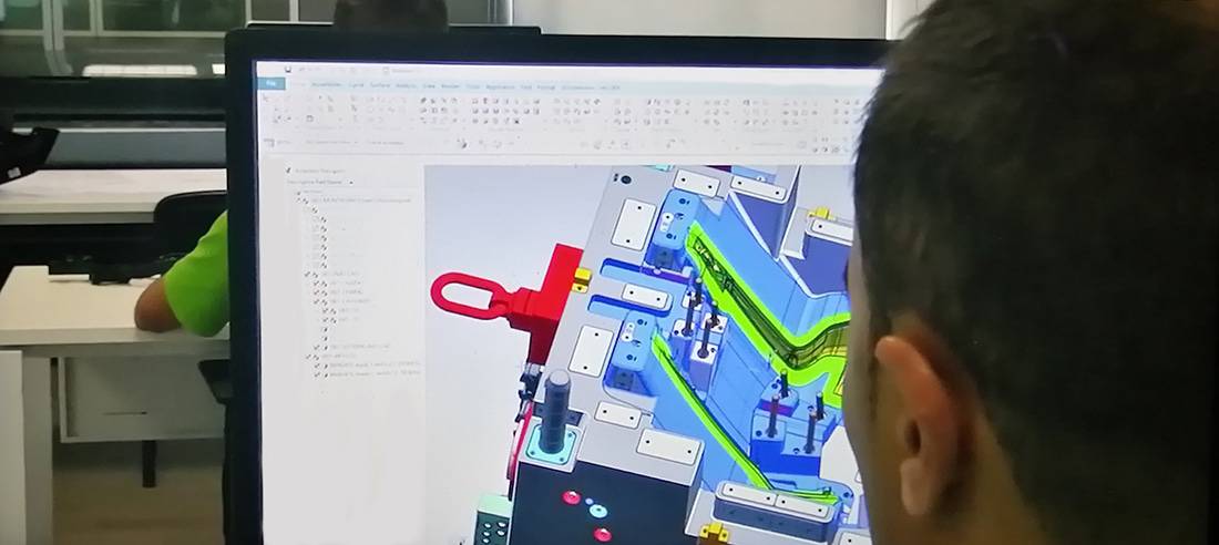
Why Partner with FMS for Mold Design?
FMS Mold Design combines decades of profound engineering expertise with state-of-the-art CAD technology to deliver high-precision tooling solutions. Supported by advanced data conversion tools and high-speed connectivity, our technical infrastructure makes global communication effortless and highly secure.
Real-Time Collaborative Engineering
We have redefined remote collaboration. Through our cloud-connected design workflows, your team can engage in real-time design reviews with our engineers at any time. We function precisely like an internal extension of your own design department—a high-touch approach that drives exceptional client satisfaction worldwide.
 FMS Mold Design Team delivers high-value, high-precision engineering solutions by seamlessly combining technical expertise with cost-effective execution. Our comprehensive services include mold feasibility studies, complete mold design and detailing, plastic part design and development, and advanced solid modeling.
Our Expertise & Capacity
The FMS engineering team consists of 10 dedicated designers, each bringing a minimum of 15 years of hands-on experience in mold design, manufacturing, and injection molding. All team members possess robust CAD/CAM/CAE competencies.
Our Design Director, David Zhang, leverages nearly 30 years of industry experience and a strong academic background in engineering. He possesses a profound understanding of European and American mold design and manufacturing standards (HASCO, DME, etc.). This deep integration of “real-world” manufacturing knowledge ensures every design we deliver is fully optimized for production, reducing lead times and costly modifications.
A Collaborative Partnership
We operate as a seamless extension of our clients’ internal engineering teams. Thanks to our diverse portfolio and decades of cross-industry experience, we adapt quickly to unique project requirements. We work closely with your engineers to deliver reliable, high-quality designs that strictly align with your standard operating procedures.
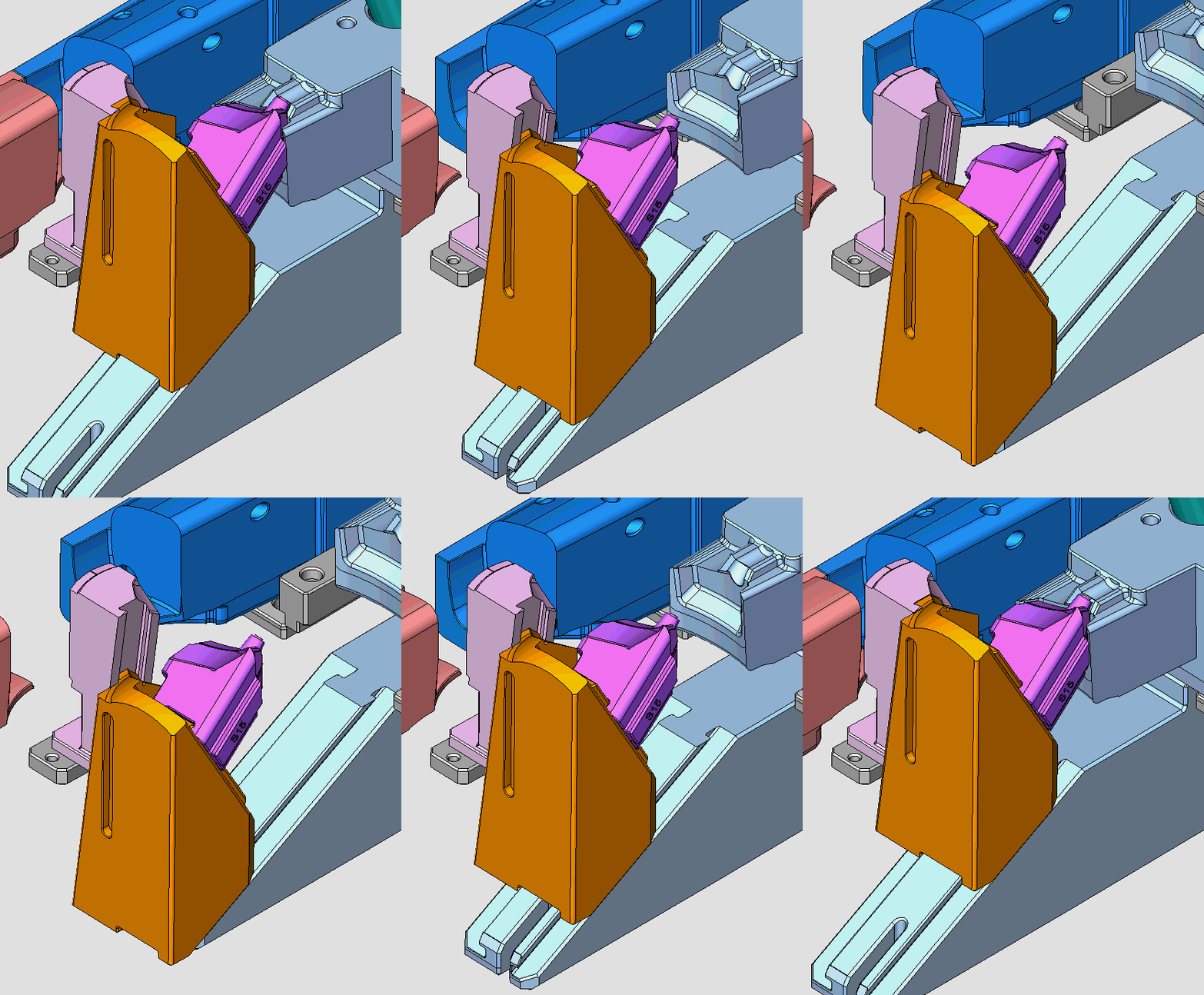
Value-Added Services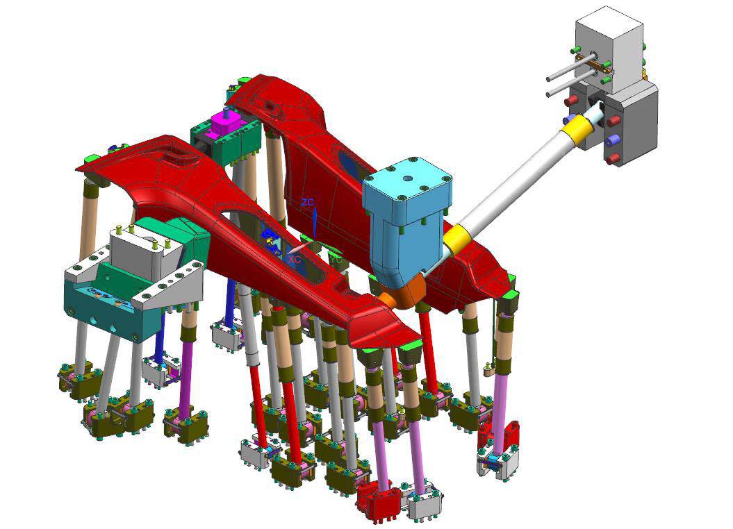
At FMS, our engineering team goes beyond standard mold design to deliver comprehensive, end-to-end technical support. Leveraging our deep industry expertise, we act as an extension of your team to provide specialized value-added services that optimize your production and fill internal capability gaps.
Our extended capabilities include:
Design for Manufacturing (DFM) and Mold Feasibility Studies / Offshore Mold Design and Third-Party Design Verification / On-Demand Engineering Resources (Additional Design Capacity)
Component Optimization Support (Assistance with Part Design) / Reverse Engineering
Design for manufacture /Mold Feasibility Studies / Designs for Off Shore Mold/Checking Designs / Additional Design Capacity /Assistance with Part Designs / Reverse Engineering
 Product Scope: Armed with a rich legacy in industrial design, our team delivers high-impact solutions across highly regulated and complex sectors. Our cross-industry footprint spans Medical Devices, Aerospace, Robotics, and Automotive, as well as Consumer Electronics, Smart Home Appliances, Workplace Technologies, and Commercial Toys. We seamlessly translate specialized technical requirements into market-ready product excellence.
Design & Engineering Flexibility
Every manufacturer operates on a unique ecosystem integrating mold design with production. At FMS, our engineering team seamlessly bridges design with advanced manufacturing methodologies. We provide fully customizable deliverables, ranging from 2D component drawings and CAD formats to precise 3D surfaces and comprehensive solid CAD data. Whether your project requires only a 2D assembly for rapid quoting or full solid CAD files with detailed hardware, cooling channels, and lifters, we adapt to your workflow. With robust data translation capabilities, we ensure seamless format compatibility—delivering exactly what you need, how you need it.
 Mold Design & Engineering Process
Robust mold design is the foundational element of a product’s manufacturing success. By engaging with our engineering team early in the design cycle, we help you optimize part geometry, mitigate manufacturing risks, and reduce overall tooling costs.
We understand that early-stage designs involve highly sensitive proprietary information. We treat your Intellectual Property (IP) with the strictest confidentiality, and we are fully prepared to execute a Non-Disclosure Agreement (NDA) before reviewing your concepts. Mutual trust is the cornerstone of our engineering partnerships.
Phase 1: RFQ & Initial Feasibility Assessment
To provide an accurate initial quotation and perform a preliminary Design for Manufacturing (DFM) review, we require the following baseline data:
• Product Geometry: Part drawings, 3D concept models, rough sketches, or physical prototypes.
• Application Environment: Product specifications, including mechanical performance requirements and operating conditions.
• Resin Specification: Intended base material (if predetermined).
• Production Volume: Estimated Annual Usage (EAU) and target production batch sizes to determine the appropriate tooling class (e.g., SPI Class 101 vs. Class 103).
During this phase, our engineering team collaborates with you to evaluate the part design for manufacturability, identifying opportunities to optimize cycle times, eliminate cosmetic defects, and minimize initial tooling investments.
Phase 2: Tooling Design & Engineering Validation
Upon successful acceptance of the quotation and project award, we require a comprehensive data package to initiate the formal mold design process:
• 2D Engineering Drawings: Fully dimensioned prints in .DWG or .DXF format.
• 3D CAD Data: Native CAD files or universal formats (.STEP, .IGES, or .X_T Parasolid).
• Material & Esthetics: Final confirmation of the raw material resin, grade, and color (Pantone/RAL or texture requirements).
• Critical-to-Quality (CTQ) Dimensions: A maximum of 5 key inspection measurements for quality control tracking.
• Project Governance: Designated primary engineering and commercial contacts for technical queries and milestone updates.
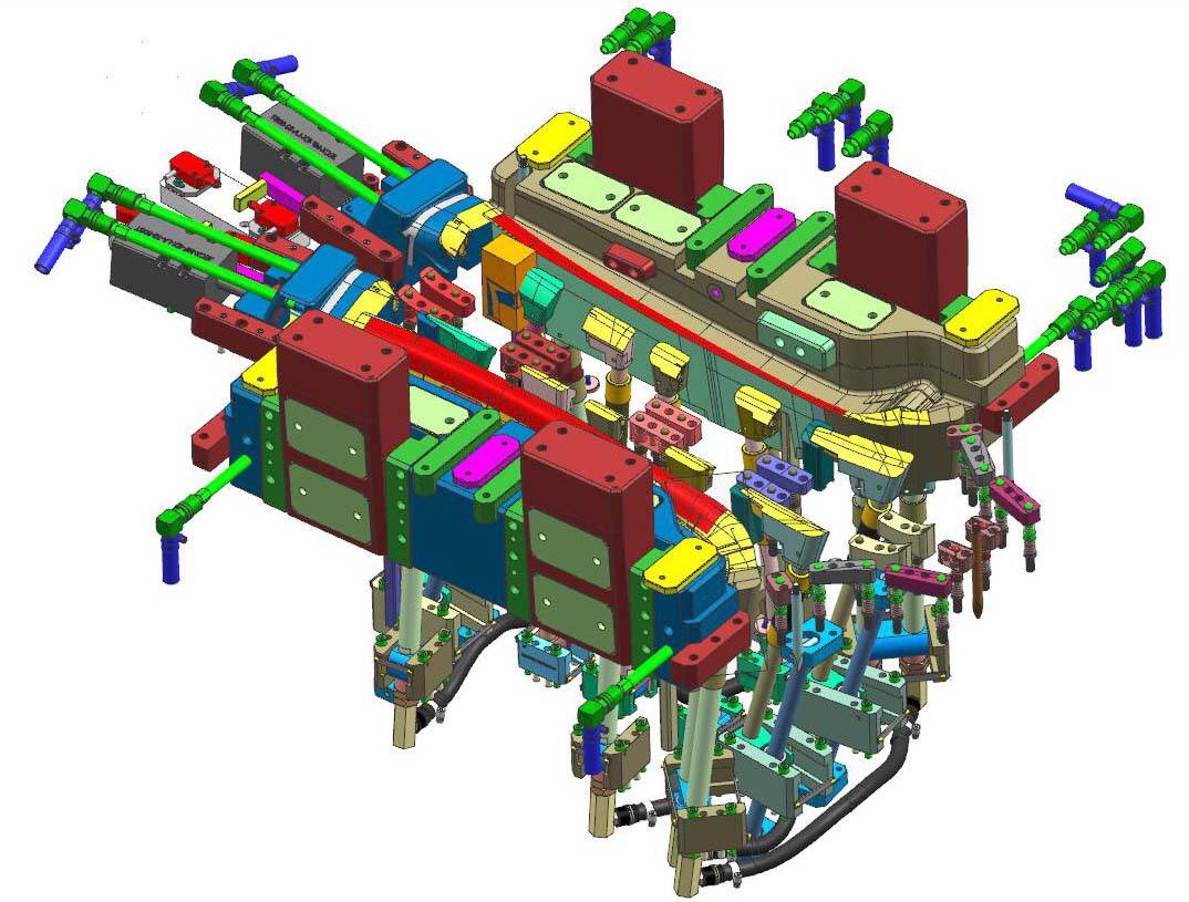 How We Execute Mold Design
Our process begins by gathering all necessary project data to provide an accurate initial quotation. We then perform a comprehensive Design for Manufacturability (DFM) review to optimize the part for production and identify potential cost savings. Following this, we generate a detailed Mold Design Specification (MDS). This guide outlines all critical requirements, including tool specifications, design standards, steel types, standard components, resin selection, shrinkage allowances, and processing parameters.
This specification guide is shared across our design, project management, and production engineering teams to ensure absolute consistency from concept to final manufacturing. Throughout production, we enforce a strict quality control workflow to maintain seamless data integrity between our 3D design models and CNC programming.
Our Stage-Gate Mold Design Process:
1. Mold Specification & Requirement Definition
2. Preliminary Tool Schematic & Concept Layout
3. Schematic Review & Customer Approval
4. Full 3D CAD Design
5. Detailed 2D Engineering Drawings & Manufacturing Documentation
Injection molding, a process that takes precision and expertise to master, reigns as the most popular technique for manufacturing plastic parts at a large scale, with unparalleled accuracy and consistency. It relies on injecting molten plastic into a meticulously designed mold, cooling it, and then ejecting the finished part.
The real game-changer in this process is the design of the mold. A well-designed mold guarantees parts that meet specifications and withstand the rigors of the injection molding process. In this blog, we delve into the best practices for injection mold design, ensuring the production of top-quality parts.
1. Material Matters: Know Thy Plastic
Before designing the mold, it’s crucial to gain a deep understanding of the material intended for injection molding. Various materials exhibit different properties that could influence the mold design. For instance, certain materials may shrink more than others when cooled, altering the size and shape of the final part. A keen understanding of the material’s properties aids designers in crafting a mold that generates high-quality parts in line with the required specifications.
2. Designing for Manufacturability: Keeping It Simple
A mold that’s difficult or expensive to manufacture can inflate production costs and prolong lead times. Therefore, designers should aim to create molds that are simple to manufacture and require minimal post-processing.
3. The Parting Line: Placement is Key
The parting line, where the two mold halves meet, plays a significant role in the appearance and functionality of the finished part. It’s essential to strategically place the parting line to minimize its impact on the final product.
4. Flowing with the Mold: The Importance of Mold Flow Analysis
Mold flow analysis is a crucial step in mold design. This simulation predicts how the plastic material will flow through the mold, informing designers to optimize mold design, improve part quality, and reduce production costs.
5. Getting in the Gate: Choose Wisely
The gate, where the plastic enters the mold cavity, influences the quality and appearance of the final part. With a range of gate types like edge gates, tunnel gates, and hot runner gates, designers must consider gate design based on the material, part geometry, and desired part quality.
6. Venting: Letting it Breathe
Proper venting, allowing air to escape from the mold cavity during injection, is critical to avoid defects such as burns, voids, and warpage. Designers should ensure the mold is properly vented to prevent these issues.
7. Designing for Cooling: Chill Out
A critical step in the injection molding process is cooling. Optimal cooling of the plastic material can be facilitated through the use of cooling channels or inserts, leading to high-quality parts with minimal defects.
8. Ejector Pin Placement: Position Matters
Ejector pins, used to remove the finished part from the mold cavity, can impact the appearance and functionality of the final part. Designers should strategically place the ejector pins based on the part geometry and desired part quality.
9. Material Quality: Strength in Substance
The mold material’s quality significantly impacts the performance and longevity of the mold. High-quality materials like tool steel and aluminum alloys are recommended for injection mold design. Although steel tools take longer to mill than aluminum, their lifespan considerably outpaces that of aluminum tools.
Injection mold design plays a pivotal role in the manufacturing industry, determining the quality, consistency, and efficiency of plastic products. For enthusiasts and professionals alike, a well-designed mold ensures smooth production, reduced costs, and high-quality outputs. Whether you’re looking to improve your understanding of injection mold design or seeking ways to refine your processes, this guide provides valuable insights. We’ll explore the importance of effective design and share the top 5 tips to master this crucial aspect of manufacturing.
1. Overview of the Importance of Injection Mold Design
Injection mold design is the backbone of any successful plastic manufacturing process. It involves creating a precise mold that forms the shape and structure of a product when molten plastic is injected into it. Here’s why it’s so crucial:
Quality Control: A well-crafted injection mold design is essential for maintaining product consistency. Proper design ensures that each part produced meets the required specifications without defects, such as warping, flashing, or sink marks.
Cost Efficiency: Effective injection mold design can significantly lower production costs. By optimizing the design for ease of manufacturing and minimizing material wastage, manufacturers can save money on materials, reduce cycle times, and extend the lifespan of the molds.
Production Efficiency: A good design minimizes the potential for production issues such as short shots, burn marks, or flow lines. This allows for faster cycle times and higher productivity, which is especially important when scaling up for large production runs.
Durability of Molds: A robust injection mold design also affects the durability of the mold itself. By considering factors like stress points, cooling channels, and proper gating systems, designers can create molds that withstand repeated use without premature wear or damage.
With the importance of injection mold design established, let’s dive into the practical tips that can enhance your design process.
2. Top 5 Injection Mold Design Tips
1. Focus on Proper Material Selection
The choice of materials for both the mold and the product is a critical first step in injection mold design. Different plastics have varying melting points, flow characteristics, and shrinkage rates, which can affect the final product’s quality. Additionally, the material used for the mold itself (such as steel or aluminum) impacts the durability and cooling efficiency of the mold. Understanding the properties of materials ensures compatibility between the mold and the injected plastic, leading to optimal performance.
Pro Tip: For high-volume production, opt for hardened steel molds as they offer durability and can handle the heat and pressure of multiple cycles. For prototyping or low-volume runs, aluminum molds can be a cost-effective and faster option.
2. Optimize Part Geometry for Moldability
The geometry of the part being produced directly affects how easy it is to mold. Complex shapes with undercuts, thin walls, or intricate features can complicate the design process, increasing the likelihood of defects. Designing parts with uniform wall thickness, avoiding sharp corners, and incorporating draft angles ensures smooth ejection from the mold and reduces internal stresses.
Pro Tip: A draft angle of 1-2 degrees is generally recommended for easy ejection, but this can vary depending on the plastic material used. Including radii in corners instead of sharp edges also helps to distribute stress evenly.
3. Design Efficient Cooling Channels
Cooling time is a significant part of the injection molding cycle, often constituting 50-70% of the total cycle time. Efficient cooling channel design in the mold can drastically reduce cooling time, leading to faster cycle times and improved productivity. Properly placed channels ensure uniform cooling, which minimizes warping and shrinkage, resulting in more accurate parts.
Pro Tip: Use conformal cooling, which follows the contour of the mold cavity, to achieve more even cooling across complex shapes. This method can reduce cycle times and improve part quality, especially in intricate designs.
4. Use Flow Simulation Software
Leveraging modern technology, such as flow simulation software, is a game-changer in injection mold design. These tools allow designers to predict how molten plastic will flow through the mold cavity, identifying potential issues like air traps, weld lines, or short shots before physical testing. This simulation helps to optimize gate placement, runner size, and cooling systems, leading to better first-time accuracy and reduced mold rework.
Pro Tip: Use softwares for detailed analysis. This will save time and resources by minimizing trial-and-error adjustments in the design phase.
5. Pay Attention to Gate Design
Gates are the entry points through which molten plastic flows into the mold cavity. The location, type, and size of the gate have a direct impact on the final product’s appearance and strength. An improperly placed gate can lead to defects like sink marks or excessive residual stress in the part. It’s essential to select a gate type that suits the part’s geometry and the type of plastic being used.
Pro Tip: Consider using hot runner systems for large or complex molds to reduce material waste and improve cycle time. Cold runner systems, while simpler, can be suitable for smaller runs or less intricate parts.
3. Conclusion
Mastering injection mold design is a blend of art and science, requiring a deep understanding of materials, part geometry, cooling systems, and the latest simulation technologies. A well-designed mold not only ensures high-quality products but also optimizes production efficiency and cost-effectiveness. By following these top 5 tips—focusing on material selection, part geometry, cooling channels, simulation software, and gate design—designers can achieve better outcomes in their injection molding projects.
For injection mold design enthusiasts, continuously refining your skills and staying updated with the latest tools and techniques is key to staying competitive in this ever-evolving field. Implementing these strategies can elevate your design process and ensure consistent success in plastic manufacturing. Happy molding!
Plastic injection molding is a widely used manufacturing process that is both cost-effective and versatile in producing complex plastic parts. It involves melting plastic granules and injecting them into a mold cavity, where they solidify and take the desired shape. A key aspect of this process is the design of the mold itself, which greatly impacts the quality, appearance, and functionality of the final product.
The fundamentals of plastic injection mold design incorporate a variety of components and features, such as gates, runners, and cooling systems, each playing a crucial role in achieving optimal results. Accurate mold design goes hand in hand with material selection and flow properties, ensuring efficient filling and solidification, as well as minimizing defects like warping and sink marks. Moreover, injection mold design caters to a multitude of industries, such as automotive, aerospace, medical, and consumer products, showcasing its immense potential.
The design and maintenance of molds are critical aspects that directly impact the quality, efficiency, and cost-effectiveness of the manufacturing process. Whether it’s creating intricate plastic components or precision metal parts, a well-designed and well-maintained mold is essential for achieving consistent and high-quality production. I want to explore the key elements of mold design and the importance of regular maintenance in the manufacturing industry.
Mold Design: The Foundation of Precision
1. Material Selection:
The choice of mold material is crucial and depends on various factors such as the type of material being molded, production volume, and desired product characteristics. Common mold materials include tool steel, aluminum, and pre-hardened steel. Each material has its own set of advantages and limitations, influencing factors like durability, heat resistance, and cost.
2. Geometry and Complexity:
The design of the mold cavity must precisely mirror the intended shape of the final product. The geometry of the mold is especially critical for intricate or complex components. Computer-Aided Design (CAD) tools are extensively used to create detailed and accurate mold designs, ensuring that every contour and detail of the final product is captured.
3. Cooling System:
Efficient temperature control is essential during the molding process to ensure proper solidification of the material and prevent defects. Mold designers must incorporate an effective cooling system into the mold design, utilizing channels and cooling lines strategically placed to maintain uniform temperatures throughout the mold.
4. Venting and Ejection:
Adequate venting is crucial to allow gases to escape during the molding process. Additionally, an effective ejection system is necessary to release the molded part without damage. Both these aspects are integral to preventing defects and maintaining the integrity of the final product.
5. Tolerance and Surface Finish:
Precision is paramount in mold design. Tolerances must be carefully considered to ensure that the molded parts meet the required specifications. Furthermore, the surface finish of the mold directly affects the appearance and quality of the final product. Proper polishing and finishing of the mold surfaces are essential for achieving a smooth and flawless finish on the molded parts.
The injection molding machine is a machine that melt plasticize the molding material inside the heating cylinder and inject this into the mold tool to create the molded product by solidifying inside it. There are several types in the injection machine. Ex. horizontal injection machine, vertical injection machine etc. In past Mold Design process was time taking as well as hectic. At first Drawing board and then 2D software were used after which patterns were made. But in this case the results were not convincing most of the times. Thus the design to market time increased immensely and also project cost required was on a higher side. Due to the technological advancement the process of Mold Design has fastened and also the results are convincing. With
the help of 3D software we can create Parametric Design, which is editable. Also we can look at number of possibilities for designing a mold. Most importantly the process of Drawing Creation for Mold Design becomes very easy. In a 3D software Visualization of our creation is easy possible. Thus the design to market time shrinks immensely also the project cost required is on lower side. The paper aims at the awareness of advances of the new age technology of 3D CAD/Mould Wizard for Mold Design
One of the most common manufacturing processes for plastic mold design is injection molding. This automated process involves injecting molten plastic into a mold cavity. The mold is then cooled down until the material solidifies, resulting in a finished product with a consistent shape and size. This method is often used for creating many high volume, affordable plastic components from toothbrushes to TV housings. It’s very quick and cost effective compared to other production methods. And to make the production process of high-volume items even more cost effective multi cavity mold design can be utilized to make many of the same components in one shot simultaneously. Such multi cavity molds obviously are a lot more expensive than single cavity molds and only interesting if annual production volumes are upwards of a million.
Injection molding is a high-precision manufacturing process that injects molten plastic into a carefully designed mold, where the plastic cools and hardens into the specified part or product. The piece is then ejected from the mold, either as the final product or as a near-final product that is sent on for secondary finishing.
The injection mold consists of two parts: the mold core and the mold cavity. The space that these two parts create when the mold is closed is called the part cavity (the void that receives the molten plastic). Depending on production needs, “multi-cavity” molds can be designed to create multiple identical parts (as many as 100 or more) during the same run.
Designing the mold and its various components (referred to as tooling) represents a highly technical and often complex process that requires high precision and scientific know-how to produce top-quality parts with tight dimensions. For example, the proper grade of steel must be selected so components that run together do not wear out prematurely. Steel hardness must also be determined to maintain the proper balance between wear and toughness. Waterlines must be well-placed to maximize cooling and minimize warping. Tooling engineers also need to calculate gate/runner sizing specifications for proper filling and minimal cycle times, as well as determining the best shut-off methods for tooling durability over the life of the program.
During the injection molding process molten plastic flows through channels called “runners” into the mold cavity. The direction of flow is controlled by the “gate” at the end of each channel. The system of runners and gates must be carefully designed to assure even distribution of plastic and subsequent cooling. Proper placement of cooling channels in mold walls to circulate water are also essential for cooling to create a final product with homogeneous physical properties, resulting in repeatable product dimensions. Uneven cooling may result in defects called “hot spots”—areas of weakness that affect repeatability.
In general, more complex injection-molded products require more complex molds. These often must deal with features such as undercuts or threads, which typically require more mold components. There are other components that can be added to a mold to form complex geometry; rotating devices (using mechanical racks and gears), rotational hydraulic motors, hydraulic cylinders, floating plates, and multi-form slides are just some examples.
The importance of mold design on the productivity of a tool is often overlooked in the design of a mold. Several areas in the mold design exist where the molder must work with the mold builder in order to optimize the productivity of the mold. A good standard for mold productivity is saleable parts out of the press per hour. Cycle time and part quality are the critical aspects of saleable parts per hour. The areas of design found to be most important for increased productivity are the sprue bushing, runners and gates, hot manifold, venting, cooling, and ejection. While each of these items is specific to the mold being built, good design for each can contribute to improved part quality and optimum cycle time.
Characteristics Critical to Mold Design
The first and most important area in mold design is the size of the sprue bushing, runners, and gates. This criterion is critical to ensure that the part can be filled stress-free, packed out, and frozen off to obtain the optimum molded part. With the use of mold flow analysis and the previous work of injection molding professionals, the correct size of the sprue bushing, runner, and gates for each material molded can be determined quite accurately. Following the guidelines for these sizes is most important, especially for the gate land length dimension, which should never be greater than 0.050? and should be as small as practical. Sprue bushings that are too small will create excessive heat and pressure in the plastic. A good starting point is to make the “O” (inlet orifice) diameter the same diameter as the main runner.
Another area that relates to the sprue bushing is the nozzle. Often, molders will change molds without ever looking at the nozzle size and making sure it is matched to the mold they are running. Many times, this will lead to excessive pressures and temperatures of the material. Always matching the nozzle diameter to the sprue bushing “O” diameter is imperative.
Too often the mold maker is left to decide the sizes of the sprue, runners, and gates and only when running the first samples does the molder learn that the sizes are not optimal. Much of this can be resolved beforehand by following the principles of runner and gate design found in the Injection Molding Handbook, as well as other reference materials. Again, runners sized too small affect the heat and pressure of the plastic and runners too large may slow the cycle for cooling time and cause unnecessary regrind.
The following chart can be used as a guideline for runner sizes, depending on part size and the length of flow of the runner. If this data can be determined from mold flow, then that is a better place to start because it uses the rheology of the material being molded.
Gate location and gate size have a large effect on the fill of the part. Gate type and location should be the first determination when designing a runner layout. This is especially true in multi-cavity molds and large parts. Many different types of gates are available to the designer. The one selected should be determined by the part geometry, as well as the effect of the gate type and location on part dimensions, material flow, and part appearance. Most problems such as part appearance, warping, long cycle times, and cycle-to-cycle part variation can be attributed to some degree to the size and location of the runner and gate. A good rule of thumb is to start with the gate at 60 percent of wall thickness for crystalline materials and 75 percent of wall thickness for amorphous materials. Gate width should be two to three times the gate height when using a tab gate.
Hot manifolds, too often, are only available to the custom molder when the customer is willing to pay for them in the initial tool. However, the advantages of hot manifolds to the custom molder, including reduced cost of molding runners and sprues, as well as handling and remolding of regrind, usually pay for a hot manifold within a relatively short period of time. The hot manifold is usually of no cost benefit to the customer, given the way plastic parts are quoted. It should be used to increase productivity for the custom molder through the elimination of regrind. The tendency is to look at the capital outlay of adding a hot manifold in the mold design. Often this makes the tool quote non-competitive.
However, as is usually the case, there is a cost to not doing something. This cost can be determined as the cost of regrind. Regrind is the most expensive material molders use because they have already paid for it, molded it, reground it, and then have to reprocess it. Sometimes it is more difficult to process than virgin material. If the yearly volume of a job is high enough, it is a good investment for the molder to include a hot manifold for the mold, even if it is at the custom molder/s expense.
Venting is a topic that is often neglected by the mold builder or at best is an afterthought. Vents need to be included in the mold design and put into the mold so that they eliminate the hot gases generated during injection. The number of vents should be too many rather than too few. An accepted rule is one vent for every inch of part periphery. However, too often, vents have lands that are too long, not polished, and do not lead to atmosphere. So while the mold may look good, if it is not made properly it really isn/t doing much to eliminate trapped gases. Going to the trouble to install proper vents both for the part and the runners will pay off in increased part quality and decreased cycle times. Many times, parts can be vented at ejector pins, slides, and lifters. Following the raw material suppliers/ recommendation for vent sizes will help eliminate flash. Finally, vents can be neglected when performing mold maintenance; they should always be checked and repaired if necessary.
Cooling takes up the greatest portion of the injection cycle and is as important to part productivity as any other aspect of the molding cycle. The size and location of water lines are critical to optimizing part quality as well as cycle time. The best cooling for the part is to make it as uniform as possible in order to eliminate molded-in stresses and non-uniform shrinkage. In reviewing the mold design, it is important to determine if there are adequate cooling lines that are optimally located to provide the most efficient amount of heat transfer for the parts in the most uniform manner possible. The water line size should be large enough to allow flow that can keep the mold at a constant temperature during molding. The use of quick connects should be specified so that they don/t restrict the flow through the water lines. Making sure each mold half is correctly plumbed so that the mold isn/t simply turned into a water heater also is important. Looping A and B halves together makes it almost impossible to keep each mold half at the same temperature.
Following the resin manufacturers/ recommended mold temperature will help optimize both part quality and cycle times. Including a plan for water flow for each mold half is always helpful to the molder and should be required in the design.
Ejection is dictated by part geometry. This is an area where the part designer and the mold designer need to work together, if possible, to ensure that the part can be ejected easily from the mold. Unfortunately, this cooperation is not always possible. Adequate draft and the elimination of any unnecessary undercuts are both extremely important to ejecting the part without distortion or stress marks. Guided ejection also is important in mold design. This feature is worth the cost in savings of damaged pins and uneven wear on ejector pins.
In more complex molds, the relationship between the ejector pins and other moving parts, such as slides or lifters, must be carefully checked so that there is no interference. Using the largest possible ejector pins is recommended to alleviate stress marks. More complicated ejector systems, such as two plates and accelerated knockouts, are used often and with great success. What/s more, most of the mold base suppliers have components that make these systems fairly economical and easy to build. The most productive ejection system is one that operates automatically. However, this is not always possible. Through the use of automation, molders have been able to develop systems that interface extremely accurately with the ejector system and do not require operators.
So many more points can be made about the importance of good mold design in relation to part productivity. But if these basics are followed, mold makers will be well on their way to making a productive mold. It is always amazing to see the same mistakes being made when there is no good reason for it, and it always seems to be at the expense of the molder. All of the above items affect the size of the processing window for making good parts. By optimizing these design features, the molder is given the best conditions possible for productively processing quality parts.
Injection molding is a high-precision manufacturing process that injects molten plastic into a carefully designed mold, where the plastic cools and hardens into the specified part or product. The piece is then ejected from the mold, either as the final product or as a near-final product that is sent on for secondary finishing.
The injection mold consists of two parts: the mold core and the mold cavity. The space that these two parts create when the mold is closed is called the part cavity (the void that receives the molten plastic). Depending on production needs, “multi-cavity” molds can be designed to create multiple identical parts (as many as 100 or more) during the same run.
Designing the mold and its various components (referred to as tooling) represents a highly technical and often complex process that requires high precision and scientific know-how to produce top-quality parts with tight dimensions. For example, the proper grade of steel must be selected so components that run together do not wear out prematurely. Steel hardness must also be determined to maintain the proper balance between wear and toughness. Waterlines must be well-placed to maximize cooling and minimize warping. Tooling engineers also need to calculate gate/runner sizing specifications for proper filling and minimal cycle times, as well as determining the best shut-off methods for tooling durability over the life of the program.
During the injection molding process molten plastic flows through channels called “runners” into the mold cavity. The direction of flow is controlled by the “gate” at the end of each channel. The system of runners and gates must be carefully designed to assure even distribution of plastic and subsequent cooling. Proper placement of cooling channels in mold walls to circulate water are also essential for cooling to create a final product with homogeneous physical properties, resulting in repeatable product dimensions. Uneven cooling may result in defects called “hot spots”—areas of weakness that affect repeatability.
In general, more complex injection-molded products require more complex molds. These often must deal with features such as undercuts or threads, which typically require more mold components. There are other components that can be added to a mold to form complex geometry; rotating devices (using mechanical racks and gears), rotational hydraulic motors, hydraulic cylinders, floating plates, and multi-form slides are just some examples.
What do the cap on your water bottle, strap on your smartwatch, and frame of your sunglasses all have in common? If they are all made out of plastic then they were all injection molded. Injection molding is a manufacturing process that has been around for over a century. In that time, the process and technology have made tremendous advancements. Similarly, mold design techniques and solutions have needed to evolve to match the technology and market needs. In the early days collapsible cores, conformal cooling, and advanced CAD softwares were beyond anyone’s wildest dreams. Today these are all standard tools in a mold designers toolbox, however, the only way these tools are useful to a mold designer is for them to gain the knowledge on how to use them. Even a simple tool, like a hammer, is just a paper weight to an individual who doesn’t know how to swing it.
we believe 3D printed mold tooling is the next big advancement in injection molding. While printed mold tooling certainly isn’t something new to the industry, it has not been widely adopted. Anecdotally, we hear all too often that someone tried out printed mold tools years ago and they just didn’t work. And historically, 3D printed tools were not made from the right materials and/or printed on the right hardware to hold up in a mold press. I dove deep into the application to understand exactly what inputs are needed to be successful. While standard inputs like material properties and printer quality are a major focus, less obvious inputs like the mold design itself has turned out to be a key contributor to successful or unsuccessful molding outcomes. One very basic principle that has guided us is that printed molds are fundamentally different from traditional steel molds. Steel molds are made out of metal while printed molds are made from a photopolymer. As a result, in order to be successful with a polymer based mold, different design strategies must be implemented.