
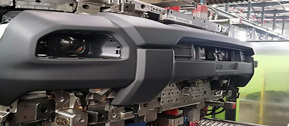
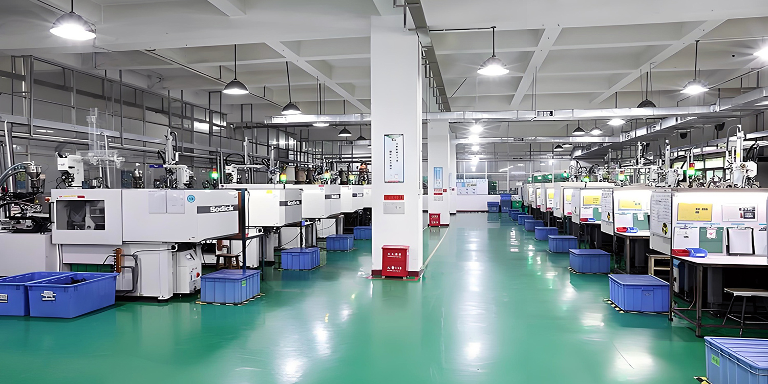
injection molding shop
FMS Molding Team Is Your Trusted Partner for Precision Mold & Injection Molding Since 2009
For nearly two decades, FMS has delivered world-class tooling and turnkey injection molding solutions to a global clientele. We specialize in custom plastic injection molding across highly demanding industries, including Medical, Automotive, Electronics, Packaging, Food & Beverage, and Outdoor Sports/Hunting.
Why Global Brands Choose FMS:
• Advanced Automation & Speed: 100% of our injection molding machines are integrated with high-speed robotics, ensuring consistent high quality, flawless precision, and minimized cycle times.
• High-Capacity 24/5 Operations: Operating on a 3-shift, 5-day schedule (with scalable weekend overtime), our workshop ensures your mass production deadlines are always met, no matter the volume.
• Engineering Excellence: Our veteran mold and design engineers bring deep cross-industry expertise, helping you optimize complex geometries for manufacturability (DFM) and cost efficiency.
• End-to-End Control: From initial tool design and steel/aluminum mold machining to final parts production, every step is managed entirely in-house by the FMS team for strict quality assurance.
Partner with FMS today to transform your complex designs into high-quality, cost-effective realities.
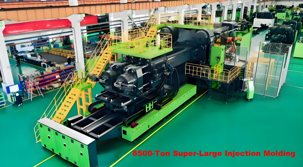
8500-Ton Super-Large Injection Molding Machine
How Does Injection Molding Work?
A special-purpose injection molding machine carries out injection molding. The manufacturing process is divided into the various steps listed below:
Step 1 – Creation of the Mold
The first step in injection molding is mold creation. The mold for the part to be manufactured is designed according to the specifications of the part’s 3D model, using computer-aided design, following several injection molding guidelines. It is then manufactured in two parts, usually using CNC machining. Molds are made from metals (mainly steel or aluminium).
Step 2 – Injection
The separate halves of the mold are placed in and held together tightly by the clamping unit of the injection molding machine. In the form of granules or pellets, the raw material is introduced into a barrel where it is heated at a high temperature and pressure till it melts. Now in molten form, the material is immediately injected into the mold cavity, filling the entire space in the mold. It then cools down and solidifies, forming the shape of the mold.
Step 3 – Ejection and Finishing
After the material has completely cooled and solidified, the mold is opened by the clamping unit and the solidified finished part is ejected. The finished part is subjected to some post-processing operations. These operations include removing excessive material and support structure, surface finishing, and, if required, painting, electroplating, heat treatment, etc.
Other Injection Molding Processes:
Over Molding
Over molding is an injection molding process that allows a part to be created from two different materials. The first material is molded and, before cooling down, the overmolding material is introduced, creating strong bonds between the substrate and the overmolding material. This technique is used to create multi-material objects with improved aesthetics and functionality, while eliminating the need for secondary operations.
Insert Molding
Insert molding is similar to over molding. In this injection molding technique a preformed object is inserted into the mold before the molten material is poured. With the point being to have the preformed material inserted into the molded object. An application of insert molding is inserting metal screw holes into plastic parts.
Metal Injection Molding
In this process, finely powdered metal is combined with wax, polypropylene binders, or other polymers to form a feedstock mix. It is then injected into the mold and left to cool. Once it solidifies, a portion of the blinder is removed using methods such as the catalytic process and the use of solvents.
Die Casting
The die casting process, also known as high-pressure die casting, is the forcing of molten metal under high pressure into a mold cavity. The process is as follows:
First is the preparation of the dies (molds), which entails the lubricating of the mold cavity to facilitate the easy removal of the casting and to control the temperature.
After that, the cast is closed and injected with molten metals under relatively high pressure between 1500 psi and 25400 psi.
Die casting products are made from nonferrous metals such as copper, zinc, aluminium, and lead.
Thin-wall Injection
This injection molding process is used to create plastic parts with very thin walls such as food packaging, parts of equipment, and lab apparatus. The sizes of these parts are larger than their thickness. This process of creating thin walls is more difficult than other processes.
Micro Injection Molding
Just as the name implies, “micro injection molding” is a molding process used to produce tiny plastic parts with weights of about 1 to 0.1 grams. This facilitates the manufacture of micro parts of various complicated geometries with maximum precision and accuracy.
Gas-assisted Injection Molding
In the production of thick plastic parts with injection molding, there’s the risk of distorted parts caused during the cooling process of the molten plastic. This is prevented from happening in gas-assisted injection. As the molten plastics solidifies, gas is introduced into the mold by gas channels, producing smooth surfaces.
The Future of Plastic Injection Molding
The future is bright for the plastic injection molding industry, with several new technologies showing a great degree of promise.
Internet of Things (IoT) technologies like sensors and automation solutions, for instance, allow for increased connectivity across the entire production system. This provides better visibility into the status of the injection molding process while also better positioning manufacturers to produce higher-quality parts at reduced costs. Automated solutions like robotic unloaders that can stack and unstack parts more efficiently can use programmable setups, sensors, and other IoT features to help shorten production timelines without sacrificing part quality.
Micro-injection molding is another emerging process that applies the mechanisms of injection molding at a microscopic scale. This is especially of interest in medical device manufacturing circles, where the technology could allow product teams to design smaller device assemblies capable of performing potentially life-saving procedures using less-invasive methods and tools.
Eco-friendly injection molding materials are increasingly in demand. While most thermoplastics can be reclaimed and reused simply by melting and re-integrating them, sustainability advocates are pushing for more ambitious goals. Out-of-the-box thinking is leading manufacturers to develop and use materials with less or no thermoplastic content, including next-generation, plant-based materials like corn- and flax-based plastics.
The Development and Emergence of Plastic Manufacturing. The history of plastic injection molding begins in 1868 when inventor John W. Hyatt patented the process of creating celluloid, a material originally intended to replace the ivory used in billiard balls. In 1872, Hyatt and his brother Isaiah patented the first injection molding machine, which used a simple plunger mechanism to push celluloid through a heated cylinder and into a mold. The device led to the development of a booming manufacturing industry that produced buttons, combs, collar stays, and other items from celluloid.
Soluble forms of cellulose acetate became available in the early 1900s, offering a much less flammable substitute for previous materials. In the lead-up to World War II, many of the thermoplastics commonly used today — including polystyrene and polyvinyl chloride (PVC) — were developed.
The Impact of World War II on Plastics Manufacturing
Developments in warfare technology, including aircraft, marine battleships, tanks, and other forms of weaponry, consumed vast amounts of raw materials during the course of the Second World War. The post-war industrial boom experienced by many developed Western countries coincided with skyrocketing demand for affordable materials that could be used to mass-produce parts. This was due in large part to how the war disrupted global shipping lanes and required the extraction of huge amounts of natural resources to manufacture tanks, ships, and other war-time products, leading to worldwide shortages of rubber and metal.
Thermoplastics presented affordable options capable of filling many of the market gaps created by these material shortages. Injection molding made it possible for manufacturers to quickly and cost-effectively manufacture parts in large volumes. As markets and supply chains worldwide shifted toward plastic, injection molding emerged as a mainstay and fixture for modern manufacturing companies.
In 1946, James Watson Hendry’s extrusion screw injection machine revolutionized the modern plastic injection molding field. The machine’s rotating screw gave the operator better control over the production process, resulting in significant improvements to the quality of the injection-molded parts. Hendry also pioneered the gas-assisted injection molding process, which made it possible to manufacture long and complex hollow parts.
During the latter half of the twentieth century, plastic materials became more advanced and competitive, offering comparable strength to some metals but at a greatly reduced weight.
Plastic production overtook steel production in terms of market share by the 1970s, and the introduction of lightweight aluminum molds in the 1990s offered a faster, more cost-effective substitute to steel tooling in some instances.
Injection molding is one of the most ubiquitous and accessible processes that you can use to manufacture your products. The versatility of injection molding that makes it such a good choice for so many products does not, however, mean that certain design aspects and considerations can get overlooked. In fact, understanding the injection molding process and the qualities of product design that are most suited to it can go a long way toward improving the efficiency of your production runs and the quality of your end products.
Taking just a few minutes to learn (or remind yourself of) some principles of design to incorporate in your injection molding designs is more than worth the effort it can save you in the future.
1) Don’t forget the necessities of the process. A quick refresher on the injection molding process: Two halves of a mold are hollowed with a negative image of your part. Hot, liquefied plastic or rubber is injected into the mold and allowed to cool. Once the plastic injection mold design is cooled, the two halves of the mold are pulled apart, and the part is released.
• During the injection process: There must be a location in the mold and on the part for the base material to be injected into. This is called the gate, and it must be removed from the finished part (this can occur automatically or manually). Gate position is important in injection molding design — you will typically want to position the gate at a thicker, intersectional area of your part where it can be removed without concern for the structural integrity of the part. Gate removal will likely also leave a scar — something to consider, because part appearance is a concern.
• During the cooling process: Your liquefied plastic or rubber material will shrink as it cools and solidifies. Be sure to take that into consideration — not only when laying out part dimensions, but also for design elements like adding radius to corners and deliberating wall thickness.
• During the part release: When the two halves of the mold are separated, there will always be what’s called a “parting line,” a natural incorporation of the fact that the mold consists of two separate halves. This is different from draft, which is caused by defects in the mold or machine, and cannot be avoided — it is best to design your part to plan for the parting line location.
2) Consider wall thickness. Some shops will tell you that they can only produce injection mold parts with a uniform wall thickness. While this can make it easier to manufacture parts, it is not integral to the process. It is, however, true that different wall thicknesses can make for a more difficult process. This is because of the cooling process mentioned above: thicker wall areas will cool and solidify more slowly than thinner areas. Combined with the shrinkage factor during the cooling process, this means that improperly designed molds and products can be subject to uncooled, still-liquefied substrate running to areas of the part where it should not be located.
Manage this potential problem by designing your part with manufacturability in mind. Thicker areas can, for instance, be located at lower parts of a mold, allowing gravity to help keep still-cooling material where it belongs. Questions? We’re always glad to offer our expertise in designing for manufacture, and can help you build the part you need while allowing for the practicalities of the process.
3) Incorporate draft. When you pop an ice cube out of a tray, you’re seeing the concept of draft at work. Each individual cube cavity in the tray is tapered to allow for a smooth exit process, eliminating the need to try and pry the cube out of the tray. Draft in your injection molded product design serves the same purpose. Adding a few degrees of taper (depending on the material and product design) means that parts will leave the mold much more smoothly, with minimum friction and scraping between the finished, cooled product and the walls of the mold. The surface of your part remains undamaged, and the process moves much more efficiently.
4) Build in texture. Rather than adding a second finishing process after injection molding to create texture on your product, you can incorporate the desired finish, pattern or texture right into the mold. By etching or milling the mold to create a finish, you gain a much greater degree of control and uniformity over the look and feel of your part, which saves some time and money by incorporating two processes into one.
5) Know your materials. This tip really plays into most of what has been covered already in this piece, but it’s important to remember: Material selection is one of the most critical considerations in designing your piece — it factors into many aspects of the process, including shrinkage factor, cooling time, flexibility and more. Different materials can have different minimum and maximum wall thicknesses, for instance, or can require different degrees of draft.
Plastic injection moulding is a very precise process that offers several advantages over other plastic processing methods. Here are just 2 benefits:
1. Precision
Plastic injection moulding is perfect for very intricate parts. Compared to other techniques, moulding allows you to incorporate more features at very small tolerances. Have a look at the image to the right. You can hold this moulding in the palm of your hand and it has bosses, ribs, metal inserts, side cores and holes, made with a sliding shut off feature in the mould tool. That’s an awful lot of features on a small part!
2. Material choice
There’s a vast amount of materials available for plastic injection moulding. A range of standard materials, but also things like antistatic plastic, thermoplastic rubber, chemical resistant plastics, infrared, biocompostable…and with colour compounding or masterbatch colouring you have an endless choice of colours as well. The moulding above is just black, but it’s made out of PPO which is an extremely rigid and flame-retardant material…..
The Injection Moulding Process
The injection moulding process involves heating & injecting plastic material under pressure into a closed metal mould tool. The molten plastic cools & hardens into the shape inside the mould tool, which then opens to allow the mouldings to be ejected or removed for inspection, delivery or secondary operations.
Injection-molded parts can feature complex geometries, and offer product designers a fair amount of design flexibility. The only caveat is that product teams must design their parts around the specific requirements of injection molding.
It’s very challenging to make design adjustments after the part has already been manufactured. As such, product designers must design the plastic part perfectly for injection molding to reduce the risk of issues with the tool design, achieve the best results, and reduce costs. To design clean, functional parts, start with these three injection molding design best practices:
1. MAINTAIN CONSISTENT WALL THICKNESSES
The number one rule of injection molding part design is managing the thickness of the mold. Non-uniform walls can cause the part to warp as the thermoplastic material cools down or cause sink marks to occur. Recommended wall thicknesses vary depending on the plastic used. For example, polyurethane (PUR) has a recommended wall thickness of 0.080 inch to 0.750 inch, while polystyrene (PS) has a much smaller range of 0.035 inch to 0.150 inch. A good rule of thumb is to keep any given mold’s wall thickness between 1.2mm and 3mm.
If the part is designed to include different thicknesses, product designers should make the transition between them as smooth as possible. This ensures that the molten plastic flows evenly inside the mold cavity. A chamfer or fillet that is 3x as long as the difference in thickness should do the trick.
Thick sections in an injection mold design can cause warping, sinking, and other defects, but sometimes they’re necessary for complex geometries. Product designers can include thicker sections in their molds while adhering to wall thickness limitations by hollowing these sections out. Including ribs in the part strengthens the hollow sections and provides stiffness.
Rib thickness varies depending on the thermoplastic used, but ribs should always be less than two thirds of the main wall thickness. If the rib is too thick, it will cause sink marks on the outer surface.
2. ELIMINATE UNDERCUTS THAT AREN’T DESIGN CRITICAL
Undercuts are features that prevent the injection-molded part from being ejected cleanly from the mold without any structural damage. Undercuts can come in a variety of forms — holes, cavities, or areas where alignment is not perpendicular to the mold’s parting line. A product designer’s best bet is to avoid undercuts altogether. They always make the injection mold design more expensive, complicated, and labor-intensive than necessary.
Still, there are a few design tricks to handle undercuts. The simplest way to fix an undercut is to move the parting line of the mold such that it intersects with the undercut. However, this tip is only applicable for designs with undercuts on the outside of the mold.
Bumpoffs, or stripping undercuts, are an option if the feature and material are flexible enough to expand and deform over the mold during ejection. The bumpoff should be far away from the mold’s support structures and have a lead angle between 30 to 45 degrees.
As a last resort, side-actions or lifters can fix undercuts when the mold cannot be redesigned to avoid undercuts. Side action cores are perpendicular inserts that slide in and out of the mold as it opens and closes.These mechanisms drive up cost and complexity significantly. Even with these solutions, it would behoove designers to steer clear of undercuts altogether and eliminate undercuts during prototyping.
3. DRAFT, DRAFT, DRAFT
Draft angles are design considerations that make it easier to cleanly eject an injection-molded part from the mold. This might sound like a non-essential design feature, but drafts are critical to manufacturing functional injection-molded parts. Drafts help prevent the part from becoming damaged upon release, lower production costs, accelerate production timelines, ensure a uniform surface finish, and provide a slew of other benefits. Without draft angles, product teams risk damaging their expensive molds and producing a large number of rejectable parts.
Drafts should be accounted for early in the design process. Draft angles will vary according to a number of factors related to the part, including wall thickness, wall depth, material, and any applicable shrink rates, texture, or ejection requirements. It’s best to apply as much draft angle as possible. Product designers should include one degree of draft per inch of cavity depth to start, adjusting for the aforementioned factors as necessary.
Even if it looks like draft might negatively impact the performance of the part, it’s always better to have draft than to not have draft. Parts can be designed with a minimum of 0.25 degrees of draft, generally, but the smallest degree of draft possible will depend on the part’s unique geometry and material.
Unless your electronic product will be marketed solely to DIYers and electronics hobbyists it’s going to need an enclosure. Most likely this enclosure will be made of plastic.
Injection molding is going be a big part of your journey to market. Regardless of your technical background you at least need to understand injection molding at a basic level.
Many entrepreneurs are surprised to learn that while the electronics will likely be the most expensive to develop, the plastic enclosure will be the most expensive to scale to manufacturing.
This is primarily due to the high cost of the injection molds. In fact, mold cost is one of the biggest expenses when taking a product from concept to market.
Injection molding is an ancient technology that has been used since the late 1800’s. Injection molding machines incorporate a huge screw to force molten plastic into the mold at high pressure. This screw drive method was invented in 1946 and is still the method used today.
Injection molding machines definitely do not have the modern, high-tech feel of 3D printing technology. There is really nothing cool about injection molding, but nonetheless it is a requirement for most hardware products.
An injection mold consists of two halves that are forced together to form a cavity in the shape of the part to be produced. Hot, liquid plastic is then injected at high pressure into this cavity.
The high pressure is needed to ensure that the plastic resin fills in every crook and cranny of the mold cavity.
Once the plastic has had time to cool, the two halves of the mold are pulled apart, and the part is ejected.
Although designing for injection molding can be quite complicated, and the cost of the molds themselves are incredibly expensive, there is one huge reason why injection molding is still used today.
No technology can beat injection molding when it comes to producing millions of identical copies of a part at an incredibly low price.
Injection molds are expensive, and you’ll most likely need a few of them, so their total cost can be quite significant. The more parts you need to produce with the mold the more expensive the mold.
This is because the mold must be designed to withstand incredibly harsh conditions. Over and over again a mold is subjected to high temperature and high pressure.
These two destructive forces act to quickly degrade the molds to the point of not producing parts of sufficient quality.
In order to tolerate this harsh environment injection molds are made from hard metals. The hardness of the metal required is typically determined by how many parts you plan to produce with the mold.
For example, a mold designed to produce 10,000 parts can be made of a much softer metal than a mold designed to produce 1 million parts.
Aluminum is a popular choice if you are producing less than 10,000 parts and works well for low volume production. Once you reach higher production volumes you will need to switch to a harder metal such as steel.
The harder the metal, the more difficult it is to make the mold, so the higher the cost. It also takes much longer to produce a mold from a hard steel. This is because molds are created by milling (i.e. carving) so a hard mold requires even harder milling tools.
If you’re an entrepreneur or boot-strapped startup with a small budget then you should definitely try to find a manufacturer that will agree to amortize your manufacturing tooling costs.
This means if your molds cost $25,000 then you could perhaps offer to pay the manufacturer back by paying them $1 extra per unit for the first 25,000 pieces produced.
Sure, this will cut into your unit profit but it’s the best financing method you can find in my opinion. It is infinitely more practical than financing your mold costs with a bank loan.
Before you endeavor to produce a part via injection molding consider a few of the following things.
Start with Financial Considerations
You’ll want to determine the number of parts produced at which injection molding becomes the most cost effective method of manufacturing.
From there, you’ll want to determine the number of parts produced at which you expect to break even on your investment (consider the costs of design, testing, production, assembly, marketing, and distribution as well as the expected price point for sales). Build in a conservative margin.
And don’t forget about entry costs. Preparing a product for injection molded manufacturing requires a large initial investment. Make sure you understand this crucial point up front.
Next, Let’s Talk Design Considerations
When it comes to part design, you want to design the part from day one with injection molding in mind. Simplifying geometry and minimizing the number of parts early on will pay dividends down the road.
When designing the mold tool, the top priority is to prevent defects during production. For a list of 10 common injection molding defects and how to fix or prevent them read here. Consider gate locations and run simulations using moldflow software
Getting Production Right for Injection Molding
Cycle time is crucial here. Minimize cycle time as much as possible. Using machines with hot runner technology will help as will well-thought-out tooling. Small changes can make a big difference and cutting a few seconds from your cycle time can translate into big savings when you’re producing millions of parts.
Tied to production is the assembly process. You’ll want to design your part to minimize assembly. Much of the reason injection molding is done in southeast Asia is the cost of assembling simple parts during an injection molding run. To the extent that you can design assembly out of the process you will save significant money on the cost of labor.
Injection Molding: The Bottom Line
Injection molding is a great technology for finished production on a massive scale. It is also useful for finalized prototypes that are used for consumer and/or product testing. Prior to this late stage in production, however, 3D printing is much more affordable and flexible for products in the early stages of design.
The main advantage of injection moulding is being able to scale up production to produce a large number of parts. Once the initial costs of the design and the moulds have been covered, the price of manufacturing is very low. The cost of production drops as more parts are produced.
Injection moulding also produces minimal wastage when compared to traditional manufacturing processes like CNC machining, which cuts away excess materials. Despite this, injection moulding does produce some waste, mainly from the sprue, the runners, the gate locations, and any overflow material that leaks out of the part cavity (also called ‘flash’).
The final advantage of injection moulding is that it allows for the production of many identical parts, which allows for part reliability and consistency in high volume production.
We love to help our customers improve their product designs by offering insights gleaned from actual case studies. we’ve gathered together four tips we want to share that can help you optimize your designs when preparing your next plastic injection molding project.
1. Design for the Material
There are thousands of thermoforming resins, and each has unique chemical and mechanical properties.
2. Design for Draft Angles
Every resin has a unique shrink rate and shrink percentage, and this determines how strongly it grips the walls of the tool after molding. This tendency to stick inside the mold must be counteracted by a sound strategy for draft angles
3. Design for Wall Thicknesses
Managing wall thickness is important for controlling stress marks. But there is also a minimum wall thickness to consider.
4. Design for Ejection
A good strategy for ejection should be part of the design process from the beginning, not an afterthought.
There are a couple of sound reasons for this, especially on thin parts. Thin part edges offer areas too small to push against for a standard pin. In some cases, stripper plates must be made instead. Stripper plates work against larger surface areas but they’re also more time-consuming and expensive to make on the mold tool.
Injection molding overseas is not cost-effective for most companies. The high shipping costs and delivery delays by overseas customs make it inefficient, so make it locally? You have likely heard negatively about the quality of plastic injection molding companies in China. However, the outsourcing industry within China has grown consistently. Many companies worldwide continue to purchase China injection molding services; some are placing large orders, and some even set up their own sourcing office in China. People prefer advanced injection molds and durable injection parts. The Chinese suppliers are reliable business partners in the injection industry.
10 important best practices for injection molding
1) Material choice. Producing high quality, consistent plastic injected modeled parts relies heavily on the chosen material. Another option is go directly to material manufacturers.
Consider mixing materials. With today’s injection molding processes, you have the option to mix materials or include additives. Additives can be a way to enhance materials to meet your needs. One additive to consider is glass. Another is carbon fiber, which will add strength and static dissipation.
2) Appropriate wall thickness. Next to your material selection, maintaining a uniform wall thickness throughout your part is critical.
Wall thickness will often determine mechanical performance, cosmetic appearance, ease of molding the part, and the cost of the part.
Achieving an optimal wall thickness is a balance between strength and weight. A 10% increase in wall thickness provides about a 33% increase in stiffness with most materials. But avoid changing wall thicknesses within a design, going from thick to thin or from thin to thick over sections.
This will be mentioned later, but ribs and curves can provide strength to a part without resorting to increased wall thickness.
3)Draft. Draft is the angle designed into your part that aids part removal from the mold. Include draft in a design to prevent sticking an ejector pin push into your parts, especially on a cavity or show surface.
Draft, annuals, and tapers all ease a part out of mold during ejection. Less draft will sometimes damage parts during ejection, a condition known as drag, especially at the parting line.
4)Runners and gates should be designed and incorporated into a mold to ensure the consistent flow of material to fill the mold at the right pressure. A gate is the connection between the runner system and the molded part. The location and size of the gate is integral to the molding process.
5)Appropriate tolerances. A part with too tight of a tolerance can lead to loss of performance or even part failure. A team skilled on advanced manufacturing technologies can advise on the best ways to safely and effectively reach exact specifications.
Many factors come into play with tolerance, including materials, part complexity, tooling, and of course the injection molding process. A tight tolerance part for injection molding is plus or minus two thousandth of an inch. Starting with a good part design will ensure your tight tolerances.
Avoid tight tolerance areas around the alignment of mold halves, the parting line, or in moving mold components such as slides. If you have two parts coming together, such as in a housing, you may want to do a beauty reveal, where you can get away with hiding the mismatch.
6) Ribs. Ribs are often used for structural reinforcement. They allow for greater strength and stiffness in parts without the need to increase wall thickness.
As a general rule, design ribs as approximately 60% of your nominal wall, or whatever the wall that the rib is joining, to minimize risk of sink. Glossy materials require a thinner rib, typically about 40% of the wall thickness. Thin ribs may be more difficult to fill in, especially once you start adding draft to them.
7) Bosses are used for locating, mounting, and assembly. Wall thickness and height are the biggest factors to consider. Wall thickness around a boss design feature should be 60% of the nominal thickness, similar to ribbing.
If a nominal part thickness is greater than one-eighth, the boss wall thickness should be around 40% the nominal wall. The height of the boss will also have a role. As a general rule, the boss height should be no more than two and a half times the diameter of the hole on the boss.
8) Reduce undercuts. An undercut is any indentation or protrusion that prohibits the ejection of a part from a mold. Most commonly, it’s called an undercut, internal, external, or inaction. Undercuts typically increase mold complexity and can lead to higher mold construction costs. Use creativity and design them in a way where actions won’t be needed.
9) Corners and transitions tie into wall thickness. Any sharp corners can cause molded in stress, just from the resin flow.
Minimize the stress by using rounded corners, adding rads on inside corners, outside corners, and trying to maintain a consistent wall thickness.
10) Thick and thin transitions. Design these as smoothly as possible. Try to avoid steps; use a ramp to improve the flow of material through your part.
Follow these best practices in the following order to ensure an easy, cost effective molded part: materials, wall thickness, tolerances, draft, ribs, bosses, undercuts and corners, and transitions.
Plastic is one of the cheapest materials to produce and it’s used by a large variety of companies and people, making it of great demand. With this high demand, it’s vital that manufacturers focus on new advancements in technology that allow machines to run longer and more efficiently, conserving energy and producing more, faster.
One key way to achieve asset longevity and maintain a sustainable environment is to use a CMMS to track key performance indicators around energy consumption and failure rates. A CMMS can ensure that manufacturers reap the benefits of predictive maintenance to make sure machines are running smoothly and address issues before they happen. Tracking energy usage can be vital in both determining issues with any equipment, as well as ensuring energy consumption is at a minimum. It isn’t just the machines that need to be sustainable; it’s important for the plastic resources, as well.
Environmental concerns are a key focus for the plastic industry. This concern goes far and beyond just equipment energy usage, but also the amount of plastic scrap produced. Both go hand in hand, as equipment that is maintained better produces at its expected quality and limits scrap plastic, as well. Strategies like using energy efficient machines and recycling scrap plastic are both efforts going into making everything more sustainable. In addition to limiting scrap plastic, many manufacturers are using an alternative to normal plastic, such as bioplastics, which are biodegradable over shorter amount of time when compared to normal traditional plastics.