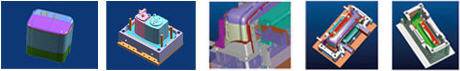
Today morning, I have a meeting with our mold designers about the mold design solution for a new product, we discuss too much design details, I want to pick out some of them to share with every one:
a) Throughout the part, it make sure to as use uniform thickness as possible, because during injection molding process, it can reduce sinking, warping, residual stresses, it is easy to get a better mold fill and reasonable cycle times.
b) Both inside and outside of the product, they should as use generous radius as possible at all corners, The smallest radius should be a material thickness.
c) One important thing we need to consider carefully is the thickness of this product, every reasonable thickness must match molding process, material and product design requirement.
d) Design all the parts with draft(taper)in the direction of mold opening or closing
in a molding process, the mold requires rapid cooling, short cycle times and minimum shot weight, then we can get a reasonable part cost
Injection-molded parts can feature complex geometries, and offer product designers a fair amount of design flexibility. The only caveat is that product teams must design their parts around the specific requirements of injection molding.
It’s very challenging to make design adjustments after the part has already been manufactured. As such, product designers must design the plastic part perfectly for injection molding to reduce the risk of issues with the tool design, achieve the best results, and reduce costs. To design clean, functional parts, start with these three injection molding design best practices:
1. MAINTAIN CONSISTENT WALL THICKNESSES
The number one rule of injection molding part design is managing the thickness of the mold. Non-uniform walls can cause the part to warp as the thermoplastic material cools down or cause sink marks to occur. Recommended wall thicknesses vary depending on the plastic used. For example, polyurethane (PUR) has a recommended wall thickness of 0.080 inch to 0.750 inch, while polystyrene (PS) has a much smaller range of 0.035 inch to 0.150 inch. A good rule of thumb is to keep any given mold’s wall thickness between 1.2mm and 3mm.
If the part is designed to include different thicknesses, product designers should make the transition between them as smooth as possible. This ensures that the molten plastic flows evenly inside the mold cavity. A chamfer or fillet that is 3x as long as the difference in thickness should do the trick.
Thick sections in an injection mold design can cause warping, sinking, and other defects, but sometimes they’re necessary for complex geometries. Product designers can include thicker sections in their molds while adhering to wall thickness limitations by hollowing these sections out. Including ribs in the part strengthens the hollow sections and provides stiffness.
Rib thickness varies depending on the thermoplastic used, but ribs should always be less than two thirds of the main wall thickness. If the rib is too thick, it will cause sink marks on the outer surface.
2. ELIMINATE UNDERCUTS THAT AREN’T DESIGN CRITICAL
Undercuts are features that prevent the injection-molded part from being ejected cleanly from the mold without any structural damage. Undercuts can come in a variety of forms — holes, cavities, or areas where alignment is not perpendicular to the mold’s parting line. A product designer’s best bet is to avoid undercuts altogether. They always make the injection mold design more expensive, complicated, and labor-intensive than necessary.
Still, there are a few design tricks to handle undercuts. The simplest way to fix an undercut is to move the parting line of the mold such that it intersects with the undercut. However, this tip is only applicable for designs with undercuts on the outside of the mold.
Bumpoffs, or stripping undercuts, are an option if the feature and material are flexible enough to expand and deform over the mold during ejection. The bumpoff should be far away from the mold’s support structures and have a lead angle between 30 to 45 degrees.
As a last resort, side-actions or lifters can fix undercuts when the mold cannot be redesigned to avoid undercuts. Side action cores are perpendicular inserts that slide in and out of the mold as it opens and closes.These mechanisms drive up cost and complexity significantly. Even with these solutions, it would behoove designers to steer clear of undercuts altogether and eliminate undercuts during prototyping.
3. DRAFT, DRAFT, DRAFT
Draft angles are design considerations that make it easier to cleanly eject an injection-molded part from the mold. This might sound like a non-essential design feature, but drafts are critical to manufacturing functional injection-molded parts. Drafts help prevent the part from becoming damaged upon release, lower production costs, accelerate production timelines, ensure a uniform surface finish, and provide a slew of other benefits. Without draft angles, product teams risk damaging their expensive molds and producing a large number of rejectable parts.
Drafts should be accounted for early in the design process. Draft angles will vary according to a number of factors related to the part, including wall thickness, wall depth, material, and any applicable shrink rates, texture, or ejection requirements. It’s best to apply as much draft angle as possible. Product designers should include one degree of draft per inch of cavity depth to start, adjusting for the aforementioned factors as necessary.
Even if it looks like draft might negatively impact the performance of the part, it’s always better to have draft than to not have draft. Parts can be designed with a minimum of 0.25 degrees of draft, generally, but the smallest degree of draft possible will depend on the part’s unique geometry and material.
The basic construction of a mold consists of a cavity and a core. The cavity is a void for the formation of the external surfaces of the injection molded part. The core is the inverse that forms the internal structures and surfaces.
Two-Plate Molds
Two-plate molds are the most common injection molding tooling because they’re versatile and cost-effective. They’re comprised of two plates: a cavity mold plate and a core mold plate. The cavity mold plate provides entry points for the molten plastic to flow from the injection unit to the mold via a sprue, and then to the runner and gate. Two-plate molds also have a gate connected to the side of the cavity (the void within the injection mold) that is the negative of the desired plastic component’s geometry.
Three-Plate Molds
Three-plate injection molds offer extra flexibility in gate positioning and reduce post-processing because they don’t require manual excess material removal. A three-plate mold differs from a two-plate mold because it has more than one parting line and three distinct plates: the clamping/stationary plate, the center plate, and the front cavity/moving plate.
With this construction, the gate connects to the base of the cavity to allow for an even distribution of molten plastic. Three-plate injection mold tooling is advantageous for center-gated parts, but due to high shear rates, they aren’t recommended for shear-sensitive materials.
Overmolds
Overmolding is a specific type of injection molding that utilizes two molds to produce a part with different plastics molded together as one unit. The two molds can be 2-plate or 3-plate molds — typically the harder “substrate” plastic is molded first and then is inserted into the overmold tooling to add a second layer of plastic, often elastomeric in nature, to the part. Overmolding is used for ergonomic and aesthetic purposes in part molding.
Injection molded plastic parts have some wonderful benefits including scalability, the ability to make simple to extremely complex parts, and uniformity, the ability to make hundreds to millions of virtually identical parts. However, the building and maintaining of injection mold tools can be expensive and making tool changes can be challenging.
Maximize the Benefits of using Injection Molded Parts
1. Uniformity is best. Constant wall thicknesses throughout your part will provide the best flow. Nominal wall thickness should be between 2-3mm. The recommended minimum is 1mm and the maximum is 4mm for conventional injection molding processes.
2. Smooth trumps sharp. Use radii when possible and avoid sharp transitions between wall sections.
3. Draft is your “frenemy.” Adding a draft angle to the faces of your part is helpful to release it from the tool, yet it can cause design challenges especially for mating parts. Recommend minimum draft angles are one degree on untextured core and at least three degrees on textured cavity surfaces.
4. Avoid surfaces with zero draft unless necessary. If you do need a zero-draft area to ensure proper part mating and tolerances, try to minimize it to just a portion of the face, not the whole surface.
5. Simpler is better. Avoid undercuts (areas that cannot be formed via the simple open/shut direction of a tool). When simple won’t work, lifter and slides allow features to be formed that are undercuts in the main pull direction. If so, leave at least 2 to 3 times the width of the feature to allow the lifter or slide to travel.
6. Transition from thick to thin. Parts will form better if plastic flows through features moving from greater to lesser wall thickness starting from the gate(s) (where the plastic first flows in to fill the part).
7. Sink (a local surface depression on a part due to thicker sections of plastic cooling more slowly) is bad. To reduce or eliminate the visibility of blemishes on cosmetic surfaces it is important to follow some recommended guidelines:
Try to avoid gates, ribs, screw bosses, etc. on the back side of important cosmetic surfaces;
Rib heights should be 3x or less than the wall thickness;
Rib bases should be 60% or less of the wall thickness.
8. Datums define territory. Use datums (features that are used as reference points to define each part) to establish part interfaces and interactions to the overall system. Using a datum structure that matches the design intent of the assembly can mean the difference between a product functioning well or not.
9. Interrogation is good. Take DFM (Design for Manufacturing) reports seriously since they convey the tool molder’s understanding of the design especially information like ejector pin locations (may conflict with planned design changes), gate locations (may cause cosmetic concerns) and parting line location (could affect interactions with mating parts). Use inspection reports to interrogate the design. Examples of DFM reports shown here:
10. Prototype early and often. Current prototyping methods, including 3D printing allows for early testing of design concepts where pieces of and/or the whole part can be modeled before building expensive tooling.
Product design begins with a consumer need: a problem that, once solved, makes life a little easier. It’s not just about making the next big thing; it’s about recognizing a demand that is not being met and finding the perfect solution that will improve everyone’s experiences. To recognize these opportunities, product designers have to think about the day-to-day experiences of consumers in the industries where they work and see where minor inconveniences fit into bigger contexts. That’s where the vision of a new product starts to take shape—when the product designer first pictures it in action.
There are a lot of steps between that first vision of a product and the moment it appears on the shelf. In order to make sure a new product actually fulfills consumer’s need, product designers should work closely with plastic injection molding partners from the onset of a new project. An experienced plastic injection molder can offer advice on material selection, develop a cost-effective plan for prototyping, help you avoid wasting resources, and get your new product out faster and more efficiently if they are involved in the design process from the beginning. Here are some tips to get you started:
1. SHARE YOUR VISION WITH YOUR INJECTION MOLDING PARTNER
Plastic injection molding is well-suited for any number of products, from high- to low-volume projects; from disposable parts to parts that need to last decades. However, the needs of your project will change the manufacturing process, equipment, and speed. Tell your injection molder how your end product will work in context, the kind of volume and production time you’re anticipating, and the functionality you need it to have. That will help them design a manufacturing strategy that’s right for you.
2. THINK ABOUT MATERIALS
The material selection process has a lot of impact on the look and function of your final product. In plastic injection molding, you have a choice between commodity resins, which are usually great for household appliances and day-to-day products like packaging materials, and engineered resins, which can be designed with the durability and functionality to stand up to harsh conditions.
3. CONSIDER THE MOLD
The tooling used in injection molding is sophisticated equipment that has significant impact on the eventual look and function of a product. Different molding processes, allow pieces to be connected to each other in different ways, and can produce different textures, colors, and patterns on a finished product. Does a metal piece need to be incorporated in your final design? Is it OK if consumers see the seam where the sides of the mold come together on the final product? These are questions you want to answer early, while you’re still considering the design of the product and the technological means to achieve it.
4. BUILD YOUR PROTOTYPE TOGETHER
Prototyping is a key part of the design process because it allows you to get feedback from potential customers, address any problems, and make changes to product design. Prototype tooling allows you to experiment with design features and make the necessary adjustments, saving money that might otherwise be wasted on high-volume runs of faulty products. The prototype and testing phase can also help build your brand develop consumer interest in your product before the first full run.
5. SHARE YOUR TESTING FEEDBACK
Design is an iterative process—hopefully you get lots of good feedback in your prototype phase. Your injection molding partner can help you figure out how to incorporate that feedback while maintaining the strengths of your test run.
Product designers know that design thinking brings together the needs of real people, the technological possibilities, and the business requirements of any given situation. You know your industry and your customer’s needs, and your plastic injection molding partner knows the available technologies and logistics of manufacturing. Together, you can create a new product that fulfills your vision.
Injection molding is one of the most ubiquitous and accessible processes that you can use to manufacture your products. The versatility of injection molding that makes it such a good choice for so many products does not, however, mean that certain design aspects and considerations can get overlooked. In fact, understanding the injection molding process and the qualities of product design that are most suited to it can go a long way toward improving the efficiency of your production runs and the quality of your end products.
Taking just a few minutes to learn (or remind yourself of) some principles of design to incorporate in your injection molding designs is more than worth the effort it can save you in the future.
1) Don’t forget the necessities of the process. A quick refresher on the injection molding process: Two halves of a mold are hollowed with a negative image of your part. Hot, liquefied plastic or rubber is injected into the mold and allowed to cool. Once the plastic injection mold design is cooled, the two halves of the mold are pulled apart, and the part is released.
From this process, there are a couple of points to remember. As an overview:
• During the injection process: There must be a location in the mold and on the part for the base material to be injected into. This is called the gate, and it must be removed from the finished part (this can occur automatically or manually). Gate position is important in injection molding design — you will typically want to position the gate at a thicker, intersectional area of your part where it can be removed without concern for the structural integrity of the part. Gate removal will likely also leave a scar — something to consider, because part appearance is a concern.
• During the cooling process: Your liquefied plastic or rubber material will shrink as it cools and solidifies. Be sure to take that into consideration — not only when laying out part dimensions, but also for design elements like adding radius to corners and deliberating wall thickness.
• During the part release: When the two halves of the mold are separated, there will always be what’s called a “parting line,” a natural incorporation of the fact that the mold consists of two separate halves. This is different from draft, which is caused by defects in the mold or machine, and cannot be avoided — it is best to design your part to plan for the parting line location.
2) Consider wall thickness. Some shops will tell you that they can only produce injection mold parts with a uniform wall thickness. While this can make it easier to manufacture parts, it is not integral to the process. It is, however, true that different wall thicknesses can make for a more difficult process. This is because of the cooling process mentioned above: thicker wall areas will cool and solidify more slowly than thinner areas. Combined with the shrinkage factor during the cooling process, this means that improperly designed molds and products can be subject to uncooled, still-liquefied substrate running to areas of the part where it should not be located.
Manage this potential problem by designing your part with manufacturability in mind. Thicker areas can, for instance, be located at lower parts of a mold, allowing gravity to help keep still-cooling material where it belongs. Questions? We’re always glad to offer our expertise in designing for manufacture, and can help you build the part you need while allowing for the practicalities of the process.
3) Incorporate draft. When you pop an ice cube out of a tray, you’re seeing the concept of draft at work. Each individual cube cavity in the tray is tapered to allow for a smooth exit process, eliminating the need to try and pry the cube out of the tray. Draft in your injection molded product design serves the same purpose. Adding a few degrees of taper (depending on the material and product design) means that parts will leave the mold much more smoothly, with minimum friction and scraping between the finished, cooled product and the walls of the mold. The surface of your part remains undamaged, and the process moves much more efficiently.
4) Build in texture. Rather than adding a second finishing process after injection molding to create texture on your product, you can incorporate the desired finish, pattern or texture right into the mold. By etching or milling the mold to create a finish, you gain a much greater degree of control and uniformity over the look and feel of your part, which saves some time and money by incorporating two processes into one.
5) Know your materials. This tip really plays into most of what has been covered already in this piece, but it’s important to remember: Material selection is one of the most critical considerations in designing your piece — it factors into many aspects of the process, including shrinkage factor.
thank you for sharing your experience
as a mould designer,I appreciate your sharing, I wish that more and more mould designers do like this
Hey There. I found your blog using msn. This is a very
well written article. I’ll be sure to bookmark it and
return to read more of your useful information. Thanks for the post.
I will certainly return.
I don’t know if it’s just me or if everyone else
encountering issues with your blog. It appears as
though some of the text on your content are running off the screen. Can somebody else please comment and let me know if this is
happening to them too? This may be a problem with my browser because I’ve had this
happen previously. Cheers
It’s a shame you don’t have a donate button! I’d definitely
donate to this brilliant blog! I suppose for now i’ll settle
for bookmarking and adding your RSS feed to my Google account.
I look forward to fresh updates and will talk about this site with my Facebook group.
Chat soon!