
There are many many sharp corners in every plastic product, what does a sharp corner mean? Sharp corners greatly increase the stress concentration during injection molding.it could lead to failure of plastic parts, especially for the high amount of stress concentration. So generally, as a mold or plastic produce designer, when he or she meet that kind of sharp corner, they need to be radiused, The stress concentration factor varies with radius, for a given thickness. Do you know how to evaluate it?we will discuss it in the next time.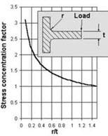
The sharp corners should be avoided in the plastic parts, as it can impede from plastic melt flow, causing flaws on parts. Meanwhile, stress concentration can be easily generated in the sharp corners and further reduces the strength of parts. Therefore, adding radii in sharp corners is suggested. There are 3 design tips about adding radii.
1. The outside sharp corners
The design of outside sharp corners is as the figure.
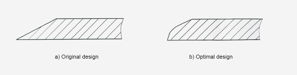
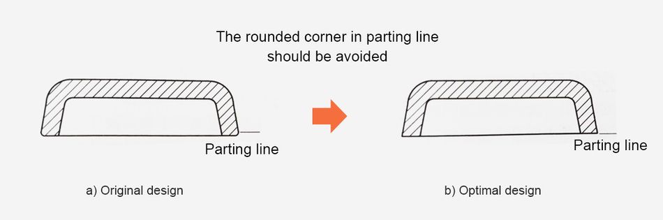
Of course, not all outside sharp corners should have radii. For example, the rounded corners in the parting line could complicate the mold configuration, increase the mold cost, make the breakage, and impact the appearance. The sharp corner in parting line of the parts is suggested.
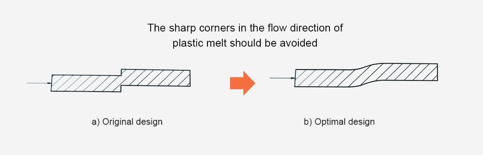
2. The sharp corners in the flow direction of plastic melt
The arrow direction in the figure is the flow direction of the plastic melt. In the original design, the sharp corner can easily cause trapped air during the injection molding, the local high temperature may degrade the parts, causing appearance defects. Adding radii is suggested to ensure the flow of plastic melt.
3. The sharp corners in the joints of wall
Stress concentration are likely generated in the sharp corners of parts. And sharp corners are easily appeared in the joints between the main wall and side wall of the parts, the joints between wall and ribs, and the joints between wall and pillars.
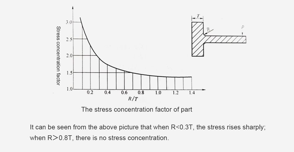
The relationship between the sharp corners and the stress concentration factor is shown in the below figure (T=Wall Thickness, R=Radii, p=the load borne by the part)
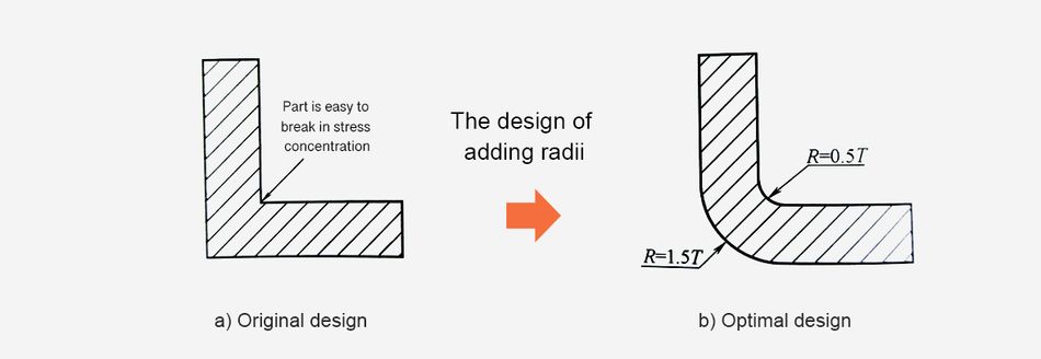
The inside radii in joints of part section should be 0.5T, and the outside radii should be 1.5T. This is to ensure the uniform wall thickness and reduce the stress concentration in part joints, as shown in the figure. Of course, the radii should not be too big, otherwise it may cause the thick wall, and generate shrinkage.
Sharp corners greatly increase the stress concentration.This high amount of stress concentration can often lead to failure of plastic parts.Sharp corners can come about in non-obvious places. Examples of this are a boss attached to a surface, or a strengthening rib. These corners need to be radiused just like all other corners. The stress concentration factor varies with radius, for a given thickness.
The stress concentration factor is quite high for R/T values lesss than 0.5. For values of R/T over 0.5 the stress concentration factor gets lower.The stress concentration factor is a multiplier factor, it increases the stress.
Actual Stress = Stress Concentration Factor K x Stress CalculatedThis is why it is recommended that inside radiuses be a minimum of 1 x thickness.
In addition to reducing stresses, fillet radiuses provide streamlined flow paths for the molten plastic resulting in easier fills.
Typically, at corners, the inside radius is 0.5 x material thickness and the outside radius is 1.5 x material thickness. A bigger radius should be used if part design will allow it.
Sharp corners greatly increase stress concentration, which, when high enough, can lead to part failure. Sharp corners often come about in non-obvious places, such as a boss attached to a surface, or a strengthening rib. The radius of sharp corners needs to be watched closely because the stress concentration factor varies with radius for a given thickness. As illustrated in the chart to the left, the stress concentration factor is high for R/T values less than 0.5, but for R/T values over 0.5 the concentration lowers. The stress concentration factor is a multiplier that greatly increases stress. It is recommended that an inside radius be a minimum of one times the thickness.
In addition to reducing stresses, the fillet radius provides a streamlined flow path for the molten plastic, resulting in an easier fill of the mold.
At corners, the suggested inside radius is 0.5 times the material thickness and the outside radius is 1.5 times the material thickness. A bigger radius should be used if part design allows.
Geometry plays a very important role. You have to balance aesthetic and functionality, keeping in view manufacturability: sharpness increases molding difficulty, tool wear, and risk of defects.
Geometry includes everything: part shape, features like ribs, bosses, holes, parting lines, draft, and wall thickness transitions. How these geometries relate will determine if corners are practical or need special treatment. E.g., placing a sharp edge near a rib intersection or near a gate may cause localized fill or cooling problems.
From a Design for Manufacturing (DFM) perspective, assume all internal and external corners will have fillets unless function dictates otherwise. DFM pushes for consistency in radii across similar features to avoid unpredictable variation.
You should also evaluate tool machining capabilities. Sharp internal corners often require EDM; very small fillets or very sharp external corners increase tooling cost and wear. The DFM practice is to design corners in ways compatible with standard milling/EDM capabilities to reduce costs.
Sharp corners may give a design a defined look, but in some manufacturing processes, they may signal trouble. Injection molding is one of the clearest examples where sharp edges add more problems than benefits.
If you had closely looked at molded plastic parts, you may have noticed that sharp edges are rarely present. That’s not an oversight but a deliberate design decision made based on molten material flow, cooling rate, and interaction with the mold.
I want to explore the challenges of adding sharp corners in injection molding, the main types of corners on injection molded parts, and the design rules that help create aesthetically and structurally good plastic parts.
Designing for injection molding, especially sharp cornered parts, is a precise engineering task. It often requires multiple revisions, simulations, and trial runs before achieving the right balance between manufacturability and performance.
Sharp corners create areas of high stress concentration, which can lead to part failure or reduced durability. The stress concentration factor is particularly high when the radius-to-thickness (R/T) ratio is less than 0.5. This concentration of stress can significantly weaken the part, especially under load or impact.
Difficulties in Mold Filling:
Sharp corners impede the flow of molten plastic during the injection process. That will lead to incomplete filling of the mold cavity and short shots. Trapped air pockets will cause voids or surface defects. Local high temperatures may degrade the material. Injection pressure requirements will be increased.
Ejection Problems:
Parts with sharp corners are more likely to stick to the mold during ejection. This can cause damage to the part during removal. The cycle time will be increased due to difficult ejection. And the mold will easy to wear and tear.
Increased Risk of Part Failure:
The combination of stress concentration and potential molding defects significantly increases the risk of part failure. This is particularly true for materials sensitive to stress during molding, such as nylon and polycarbonate.
Reduced Impact Strength:
Sharp corners dramatically reduce a part’s ability to withstand impact loads. For example, increasing the inside corner radius from 0.010 inch to 0.020 inch can notably improve impact strength.
The radius on corners has two primary functions. It improves the flow of the melt around a corner, which allows a cavity to be filled at lower injection pressure. This, in turn, results in less molded-in stress throughout the part. Corner radii also make molded parts stronger by distributing any stress on the corner over a broader area on the part. In other words, there is more plastic material to absorb the load.
Sharp corners often lead to defects and stress concentration in plastic parts, which can cause fractures under load or impact. Larger rounded corners (fillets) offer a solution to this problem. They not only reduce stress concentration but also facilitate smoother flow of the plastic during molding and easier ejection of the finished product.
If the internal corner is rounded and the external corner is sharp, the area at the turn will still be thicker than other parts, leading to shrinkage. A solution is to round both internal and external corners to achieve uniform wall thickness. In this case, the external radius is the sum of the internal radius and the base wall thickness.
The design principles for corner radii also apply to cantilever snap-fits. In these snap-fits, the cantilever arm needs to bend and fit into place. If the radius of the corner (R) is too small, it can lead to excessive stress concentration, making the product prone to breaking when bent. Conversely, if R is too large, it can result in shrinkage marks and voids. Therefore, there is a specific ratio between the corner radius and wall thickness, typically ranging from 0.2 to 0.6, with an ideal value around 0.5.
Sharp corners have their purpose – but they’re incredibly difficult to make with injection molding. That’s where radius design comes in when creating the mold for your part. So, what is a radius, and why is it important?
WHAT IS A RADIUS?
A corner radius (corner radii if there is more than one) is a technical term for smoothing out or rounding any sharp corner in a design. Internal radii are used for inside corners and external radii are used on outside corners. The general rule is to use a radius equal to at least 0.5 times the adjacent wall thickness.
FILLET RADII
An internal radius is also called a fillet radius. They are designed into molds to improve the quality of the part, increase load-bearing strength, and improve the injection molding process. Fillet radii are usually found on inside corners or the bottom of a compartment, and they can be used between ribs, bosses, and gussets to connect them to walls for better strength.
ROUND RADII
An external radius is called a round radius. It’s the rounding of outside corners for the same purposes as fillet radii.
WHY IS RADIUS DESIGN IMPORTANT?
While rounding out sharp corners makes a part easier to handle, incorporating radii into your design also helps improve the quality and stability of your part. Why?
Due to the way that molten plastic fills a mold, it’s incredibly difficult to fill sharp corners in a mold. External radii help make sure the whole mold is filled, ensuring better part quality.
Additionally, as a part cools, it shrinks. If it has to shrink around a sharp angle, it adds additional stress to the part that can lead to cracking.
For these reasons, it’s also important for sharp corners at the base of ribs, bosses, and gussets to have a radius design, since they help to offset stress points.