Both the shrink mark and shrinkage porosity are defects of injection products due to the molding shrinkage at thick walls where no sufficient follow-up compensation is made. During the injection process, the surface layer of products often condenses first, followed by the center layer, which will cause sinking on the surface of parts with thick walls, thereby producing obvious inner concave is called shrink mark and the large concave is called depression;
conversely, when parts with thick walls have condensed and when the surface intensity and rigidity are large enough to resist the shrinkage stress resulted from the subsequent shrink of the center part, a large shrinkage porosity or a series of minute shrinkage holes will form inside thick walls. Usually when such shrinkage porosities or holes appear, depression will more or less occur at the surface of products.
Although shrink mark has no impact on the structural intensity of products, it will cause rather obvious visual defect on the surface whereof; depression influences both surface quality and structural property of products; shrinkage porosity can bring bad effect on the structural property of products. The three defects usually occur at parts with relatively thick walls or at hot spot of products such as the back of lug boss, stiffening rib as well as straight gate of spure.
During actual production, optimization of structure and material of product, the injection technics as well as mold structure are usually adopted to avoid shrinkage porosity and meanwhile to control the surface shrink mark of products at the minimum degree that can be accepted by users.
The Crucial Role of Material Shrinkage in Creating Sink Marks
Now, let’s talk about material shrinkage in the production of plastic parts. It’s a natural phenomenon in the injection molding process. As the plastic material cools and solidifies, it contracts. It’s like when you leave a balloon out in the cold, and it shrinks. Different plastic materials have different rates of shrinkage.
If you don’t account for this during the design phase, this shrinkage can lead to sink marks injection molding defects. It’s like forgetting to adjust your baking time when you switch from a metal to a glass baking dish. So, it’s essential to understand the shrinkage rate of the chosen material and adjust the mold design accordingly to prevent these defects.
Exploring the Relationship between Molding Conditions and Sink Marks
Molding conditions and sink marks, they’re more connected than you might think. Factors like injection speed, injection pressure, and holding time can influence the occurrence of these defects.
For instance, a rapid injection speed might trap air within the mold, leading to voids and, subsequently, sink marks. It’s like when you whip your cake batter too fast and incorporate too much air. On the other hand, insufficient injection pressure might not fill the mold cavity completely, resulting in sink marks on the molded part. It’s like not filling your cake tin enough, leading to a flat cake.
How Incorrect Melting Temperatures Lead to Sink Marks in Injection Molding
Melt temperature is a critical parameter in the injection molding process. If the molten plastic is too hot, it needs longer cooling time, leading to sink marks. It’s like trying to freeze boiling water; it’s just not going to happen quickly. On the flip side, if the molten material is too cool, it might not fill the mold cavity completely, leading to short shots and, you guessed it, sink marks.
The key is to find the Goldilocks zone for your melting temperature – not too hot, not too cold, but just right. This optimal temperature ensures the molten plastic flows smoothly into the mold cavity, fills it completely, and cools at a rate that minimizes the risk of sink marks injection molding defects.
The Influence of Pack and Hold Time and Pressure on Sink Marks Formation
In the world of injection molding, pack and hold time and pressure are like the secret ingredients in a recipe. They play a critical role in the process and can significantly impact the formation of sink marks.
Pack and hold time is the period during which the molten plastic is packed into the mold cavity under pressure to compensate for shrinkage as the material cools. It’s like the time you leave your cake in the tin after it comes out of the oven to let it set. If the hold time is too short, the molten plastic might not have enough time to fill the thicker sections of the mold, leading to sink marks. On the other hand, if the hold time is too long, it can lead to overpacking and excessive internal stresses, which can also result in sink marks.
Now, let’s talk about holding pressure. It’s like the pressure you apply when you’re icing a cake. Too little pressure, and you might not cover the whole cake. Too much pressure, and you might end up with a mess. In injection molding, insufficient hold pressure might not compensate for the material shrinkage, leading to voids and sink marks. Conversely, excessive hold pressure can cause overpacking, leading to warpage and, again, sink marks.
So, it’s all about finding the right balance. The key is to apply the proper packing pressure and maintain the optimal hold time to ensure the mold cavity is filled completely and uniformly, thereby minimizing the risk of sink marks.
High Mold Temperature: A Common Culprit for Sink Marks
Mold temperature is another factor that can influence the formation of sink marks. Excessive temperature can cause the plastic material to cool and solidify slowly, leading to differential shrinkage and sink marks. It’s like trying to cool a hot pie in a warm room; it’s just going to take longer.
On the other hand, a low temperature of the insert can lead to a rapid cooling rate, which might not give the molten plastic enough time to fill the thicker sections of the mold, leading to sink marks. The goal is to maintain an optimal mold temperature that allows the plastic to cool at a rate that minimizes the risk of sink marks.
The Role of Part Geometry and Mold Design in Sink Marks Formation
Part geometry and mold design are like the blueprint for your injection molding project. Similar to how architects need to consider the purpose and function of a building when drawing up plans, injection molders also must consider the ultimate purpose and functionality of the plastic parts.
But here’s the catch — failing to design the part and the mold correctly could lead straight to a sink mark disaster. For instance, incorporating thicker wall sections without appropriate considerations for cooling can result in localized shrinkage. Consequently, it may lead to sink marks in the injection molded part.
Complex part geometries can also compound the potential for shrinkage and the formation of sink marks. It’s like attempting a multi-level architectural marvel without considering the weight distribution — can lead to structural instability.
Balancing Rib and Wall Thickness to Minimize Sink Marks
The wall thickness and harmony between ribs are another crucial element in the generation of high-quality injection molded parts. Unbalanced thickness can result in differing rates of cooling and shrinking, causing sink marks at the junction areas in an injection molded part.
Imagine you’re building a model car. If you make certain parts too thick compared to others, it could lead to a disfigured end product – the same principle applies to sink mark injection molding. A well-thought-out design, keeping maximum uniformity in wall thickness, can go a long way in maintaining the part’s aesthetics and structural integrity.
Importance of Gradual Slope at Rib Base in Sink Marks Prevention
To prevent sink marks, one of the design practices includes the use of a gradual slope at the rib base. Just like ensuring a smooth transition between different sections of a sculpture, providing slopes at rib bases ensures better material flow, thereby reducing stress concentration.
When the plastic melts and gets injected, a gradual slope can reduce abrupt directional changes that the molten plastic might experience, hence decreasing the likelihood of sink mark injection molding defects.
The Optimal Boss Design to Reduce Sink Marks
Bosses are like the captains of the plastic parts, they’re designed to provide structural support, assist in alignment, or act as attachment points. However, improperly designed bosses can lead to sink marks.
The optimal boss design includes maintaining uniform wall thickness, using a gradual transition between sections, and considering the use of core-outs where possible. This reduces differential shrinkage, thereby minimizing the risk of sink marks injection molding defects.
Ensuring Uniform Wall Thickness to Avoid Sink Marks
One of the primary culprits to making sink marks in injection molding is the differential cooling rates between the outer portion of the plastic part and its thicker sections. The key design principle in the prevention of sink marks is ensuring uniform wall thickness. Variations in thickness can result in differential cooling and shrinkage, leading to the formation of sink marks in thicker regions.
Think of it like freezing a container full of water. The sections that are thinnest will freeze first, while the thickest sections will take a bit longer. That’s kind of what’s happening inside the mold during an injection molding process.
Practically, maintaining a uniform wall thickness might not always be achievable due to complex part geometries. In such cases, it’s essential to transition gradually from thinner sections to thicker sections to facilitate even cooling and avoid sink marks.
Corrective Measures for Sink Marks: Material and Mold Temperature Adjustments
Sometimes, even when you’ve done everything right, you might still end up with sink marks injection molding defects. But don’t panic! There are corrective measures that can help. Adjusting the material and mold temperature is one such measure.
Implementing Design for Manufacturability (DFM) to Prevent Sink Marks
Implementing DFM, or Design for Manufacturability, is like cooking with a well-written recipe. It can save you a lot of time and unnecessary steps, not to mention reducing defects like sink marks. The DFM approach integrates product design and process planning into one common activity.
Essentially, DFM aims to minimize the complexity of manufacturing operations, enhance the overall molding process, and, of course, minimize the occurrence of defects like sink marks. This approach can help to scrutinize the design of the molded part, identify areas that are prone to sink marks, and adjust those designs preemptively.
It covers everything, right from the geometry of the part to the materials chosen, and from the design phase to the execution of the injection molding process. So, essentially, it’s a comprehensive way to prevent sink marks injection molding defects.
Let’s wrap things up. Sink marks in plastic injection molding can be problematic, but as we’ve learned, they’re not inevitable. A little bit of attention to materials, process conditions, and most importantly, part and mold design, can prevent these little buggers from showing up in your plastic parts.
Whether it’s ensuring that your molten plastic flows smoothly into the mold cavity or balancing rib and wall thickness, these considerations can make a substantial difference. And by implementing best practices, such as using a gradual slope at rib bases, the optimal boss design, and Design for Manufacturability (DFM) principles, you can steer clear of sink marks.
Avoiding sink marks isn’t just about making parts look good. It’s about maintaining their structural integrity, reducing production costs, and protecting your brand’s reputation. And with the insights we’ve discussed, you’ll be well on your way to achieving high-quality, sink mark-free injection molded parts.
Sinks are common injection molding defects that occur in thicker sections of molded parts. Since thicker sections contain more plastic, they will naturally take longer to cool. The outer portion of the part that is in contact with the mold steel cools much faster than the internal part. As the molecules in thicker sections begin to contract, they pull in on themselves, leaving a defect known as a sink. The good news is, there are several ways to prevent them.
Here are 5 ways you can prevent sinks from happening in your injection molded parts.
1. Check Your Melt Temperature
In processing, one of the first things we want to verify to correct sinks is melt temperature. The melt temperature should be within the resin manufacturer’s recommended range. If it is too high it will take longer to cool the parts, leading to sink marks.
2. Make Sure You Have Enough Pack and Hold Pressure
If material temperature is not the cause of the sinks, we then begin to look at pressures, specifically pack and hold pressures. Pack and hold pressure (or second stage pressure) is used to compensate for shrinkage inside the mold. Thick sections of the mold will need more plastic in order to retain their shape. If there is not enough plastic in that thicker section when the molecules cool, a sink is generated.
Increasing the pack and hold pressure may increase the amount of plastic at the sink. If we can get enough plastic into the area with enough pressure, the molecules will no longer pull in on themselves, eliminating the sink.
3. Adjust Pack and Hold Time
Another processing problem that can cause a sink mark is when the pack and hold time (or second stage time) is too low. We may have the right amount of pressure, but not the appropriate amount of time. In most cases, we want to ensure our pack and hold time is long enough to seal the gate of the part, meaning plastic at the gate is solidified so no plastic can enter or exit the cavity.
Think of people in a room. If the room is crowded and the door is left open, people will naturally exit the room. Plastic is no different. If we do not wait until the gate is solidified, plastic will exit the cavity. Once plastic leaves the cavity, we can no longer compensate for the shrinkage that will occur during cooling. Increasing the hold time and verifying the gate is sealed can help prevent sink marks.
4. Avoid Excess Mold Temperature
Excess mold temperature can also lead to sinks. If the temperature of the mold is set too high, it can affect the time it takes for the gate to seal. You can find the recommended mold temperature from the resin manufacturers. Once the appropriate temperature range is established, verify that the mold is plumbed correctly and that no water flow issues are occurring.
5. Ensure Proper Part and Mold Design
Sinks can also occur due to part and mold design. Because sinks often occur in thicker sections of a part, the best approach in part design is to create nominal wall thickness, but this is not always possible. If the part is in the design phase, the thickness can be reduced by coring out those sections or by creating multiple thinner sections.
Corners can be problem areas too, since the joining of two walls can lead to increased thickness. Rounding outer and inner corners can help maintain constant wall thickness and eliminate sink.
One of the critical aspects of mold design in relation to sinks is water line placement. The thicker sections usually get adequate cooling at the part surface, however the inner portions of the thick area are often neglected. Getting water to inner portions of the thick section may be challenging but can improve sinks, part quality, and possibly cycle time.
Remember, the goal is to provide uniform cooling to the area of the part where the sink occurs.
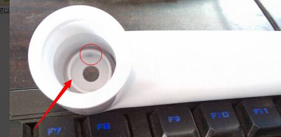
Sink mark is a defect looks more like a dimple or groove on the surface of injection molded parts with variations in wall thickness, typically found in a thicker area of a component. The degree of visibility of a sink is dependent on its depth, the color of the product, and its texture. Sink marks happen when areas of hot liquid resin cool and shrink at different rates. Sink marks can originate from processing methods, tooling design, part geometry, and material selection. Most often, sinks don’t affect structural integrity or strength. Look at where the sink is. If the sink appears in a hidden place or will be covered by another part, and if it doesn’t impact the structural integrity or strength, then you can just leave it there. Labels also use for covering a sink mark. A texture is also proving effective for hiding a sink mark. It can provide camouflage, but it can’t cover a sink mark. If, however, the sink shows up somewhere visible, you’ll need to take a hard look at what is causing it.
As a manufacturing supplier, we suggest eliminating the sink mark on molded parts before it occurs, instead of looking for solutions in a rush when the sink mark appears. Looking for solutions means that the injection molded part design has to be modified, or engineers have to adjust the mold gates or runners. The measures mentioned not only increase the production cost but prolong the product development cycle. The worst thing is with all efforts have been made, you’ll have to make the compromise that sink marks are still there. 3D modeling provides a powerful capability for plastic part designing. In Solidworks, we can use thickness analysis for the assessment of our part. The plastic software makes possible feature modification and packing size. It will be helpful for the reduction of the sink mark.